A familiar production problem rarely announces itself with a dramatic equipment failure. More often, two operators load the same part into a benchtop fixture, one shifts a locator by feel, and the next batch takes longer, needs more inspection, or produces scrap that nobody can trace to a single mistake. The fixture still “works,” but it no longer protects the process.
That is when manufacturing leaders start asking whether they need custom tooling systems. The right answer usually isn't a choice between doing nothing and buying a fully automated cell. It's a sizing decision. A manual fixture with better gauging may be enough for one operation, while another process needs powered clamping, sensors, or automated loading.
Custom tooling has always been more than an accessory. The Congressional Research Service history of the U.S. tool-and-die industry traces modern American tool-and-die practice to Eli Whitney's late-eighteenth-century work with specialized tools and dies for interchangeable firearm parts. That same principle still governs a modern production cell: convert product requirements into a repeatable physical process.
Table of Contents
- Why Production Teams Are Rethinking Their Tooling
- What Custom Tooling Systems Actually Are
- Custom Tooling vs Off-the-Shelf Tooling
- Engineering Requirements Behind a Reliable Custom Tool
- GMP, the 2026 QMSR, and Tooling Design
- Costs, Lead Times, and the Right Level of Automation
- Working With a Custom Tooling Partner
Why Production Teams Are Rethinking Their Tooling
On a busy shop floor, the first warning sign is often a cycle time that has drifted beyond takt without anyone changing the work instruction. An operator reaches around a clamp, rotates a part to find the correct face, checks alignment visually, and repeats the sequence for every unit. The second warning sign is variability between shifts. Experienced operators compensate for a weak fixture, while newer operators follow the same instructions and get a different result.
Customer audits make that gap visible. A reviewer may ask how the line prevents incorrect seating, how the team verifies a critical feature, or how a fixture revision is controlled. “The operator knows how it goes” isn't a process control. It's a dependency on individual memory.
Product changes create a third pressure point. A general-purpose jig that handled one housing may not support a revised flange, new connector, altered pickup location, or tighter datum scheme. Adding shims can rescue a prototype, but a stack of informal modifications creates tolerance uncertainty and makes maintenance harder.
Practical rule: If operators must remember how to make the fixture work, the process probably needs more engineering, not more reminders.
The historical case for tooling remains strong because purpose-built dies, fixtures, gauges, and workholding systems establish interchangeability and consistency. The U.S. tool-and-die sector recorded $11.7 billion in sales in 2010, while the number of U.S. tool-and-die establishments fell 36% between 1998 and 2010, according to the CRS source above. That contraction highlights a practical concern for manufacturers: specialized design and machining capability is strategically important, but it can't be treated as an automatic, always-available commodity.
For a small or midsize manufacturer, the decision often sits between several production realities:
- Manual work remains appropriate when product mix is high and the operation is simple.
- Assisted tooling helps when clamping, lifting, gauging, or orientation causes delays.
- Semi-automatic equipment fits repeatable processes where an operator still needs to load and unload the part.
- Full automation makes sense when volume, staffing constraints, product stability, and validation effort justify a more integrated cell.
A useful starting point is to quantify the current loss without assuming the answer is a robot. Time studies, first-pass yield, changeover observations, ergonomic reviews, and audit findings show whether the constraint is positioning, clamping, inspection, handling, or the process itself. Guidance on reducing production costs through process-focused improvements is most useful when it leads to that kind of evidence-based sizing.
What Custom Tooling Systems Actually Are
A catalogue clamp solves a narrow mechanical problem. A custom tooling system solves the interaction between a part, a process step, an operator, and the surrounding equipment.
Think of it as the engineered middle ground between a standard clamp bolted to a bench and a purpose-built robotic cell. The system is designed around one product family, one operation, and one defined production environment. It can hold the part, guide the work, prevent incorrect loading, verify a condition, and communicate with equipment around it.
A complete system may include:
- Locating pins, datums, nests, and hard stops that establish the part's reference position.
- Toggle clamps, pneumatic clamps, hydraulic actuators, or cam mechanisms that apply controlled force.
- A fixture body, base plate, modular inserts, and quick-change components.
- Sensors that confirm presence, orientation, clamp state, or completion of an in-process check.
- Gauges, probes, error-proofing features, and operator prompts.
- Drawings, bills of material, inspection records, calibration requirements, work instructions, and validation evidence.
The distinction between a fixture and a system matters during changeover. A fixture may hold one part correctly today, but a tooling system also defines how the operator changes variants, how the cell identifies the active configuration, how replacement components are installed, and how the organization records revisions.
Start with the process, not the hardware
Before a designer chooses a clamp or locator, the team should define the operation. What surface must remain accessible? Which features establish the datum? What force can the part tolerate? Does the operator load the component from above, from the side, or through a constrained opening? Does the process need a sensor, a gauge, or only a clear mechanical poka-yoke?
The answers determine whether the right solution is a simple manual fixture, an assisted station, or a more integrated machine. A custom workholding fixture approach should therefore begin with part prints, process requirements, operator motion, quality risks, and maintenance expectations.
Custom tooling systems also need a defined boundary. The tooling may include controls, sensors, guarding, data collection, and interfaces to upstream or downstream equipment, but those additions should serve a production requirement. A sensor that collects data nobody reviews adds wiring and maintenance without improving control.
The right level of engineering depends on production volume, product similarity, validation burden, changeover frequency, and the cost of process variation. That makes custom tooling a sizing exercise, not a binary purchase.
Custom Tooling vs Off-the-Shelf Tooling
Off-the-shelf tooling wins when speed and flexibility matter more than optimization. A catalogue clamp, standard locator, or modular plate can get a prototype into work quickly, and replacement parts are usually easier to source. For low-volume production with a stable, forgiving part, custom engineering may add cost without removing a meaningful constraint.
Custom tooling wins when the process repeats often enough for small inefficiencies to become operational losses. A part that needs precise orientation, controlled clamping, unobstructed access, or consistent inspection usually exposes the limits of generic hardware. The purchase price is only one part of the comparison.
Four decisions determine the smarter spend
Unit cost versus amortization. A catalogue component has a visible price, but it doesn't show the labor consumed by manual alignment, repeated checking, rework, or slow loading. A custom base with standard clamps may cost more at release while lowering the recurring cost of each cycle. The business case should include labor dependency, scrap exposure, inspection time, maintenance, and future changeover effort.
Lead time versus engineering scope. Off-the-shelf tooling can often be ordered immediately, but it may require workarounds at installation. Custom tooling takes design and review time, yet that effort can resolve datum strategy, access, ergonomics, sensor placement, and serviceability before fabrication. The fastest purchase isn't always the fastest route to a stable process.
Flexibility versus optimization. A generic fixture can accommodate a broad family, but flexibility often means more adjustment and more opportunity for incorrect setup. A dedicated fixture can control the critical features tightly, while modular inserts or a common base plate preserve useful variant flexibility.
Validation and change control. In a regulated process, the team must assess how the tooling affects product conformity and documented process control. A standard item may still require qualification in the application, while a custom system demands clear design inputs, verification records, revision control, and maintenance instructions.
The tooling cost discussion for manufacturers becomes more useful when it separates initial expenditure from total ownership. Ask what happens after installation, when an insert wears, a product variant changes, or a quality investigation needs evidence of the tool's condition.
A practical selection rule
Choose off-the-shelf tooling when the part family is stable, production volume is limited, tolerances are forgiving, and operators can load the part unambiguously. Choose custom tooling when the component is tight-tolerance, repeated in volume, used in a regulated process, or expected to share a controlled fixture plate across variants.
The hybrid path is often the most sensible. Standard cylinders, clamps, pins, sensors, and hardware can be mounted on a custom base with engineered datums and change parts. That combination avoids designing every component from scratch while still addressing the production risks that catalogue hardware cannot solve alone.
Engineering Requirements Behind a Reliable Custom Tool
A fixture should not reach fabrication because its 3D model looks complete. It should reach fabrication only after the engineering team has translated production needs into measurable requirements.
Fixture-development research describes a workflow that starts with workpiece geometry and process requirements, moves through setup planning and locator selection, and ends with verification and modification. The fixture-development research published by Chalmers identifies six interacting demands: stiffness, dimensional tolerance, operator operability, workpiece access, cost, and allowable development time.
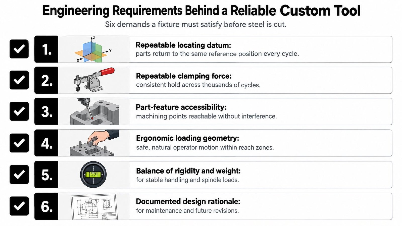
Six demands belong in the specification
Repeatable locating datum. Every part must return to the same reference position. Weak datum strategy produces dimensional drift, inconsistent machining, and inspection results that vary by operator or shift.
Repeatable clamping force. The clamp must secure the workpiece without distorting it. Excessive or inconsistent force can move a thin component, mark a finished surface, or create different results as hardware wears.
Part-feature accessibility. The tool must leave the machining, assembly, inspection, and service points reachable. A locator that improves stability but blocks a fastener or probe has only moved the problem.
Ergonomic loading geometry. Operators should be able to load, orient, clamp, and unload without awkward reaches or unnecessary lifting. An ergonomics review skipped during design frequently returns as a cycle-time bottleneck and a source of missed steps.
Rigidity balanced with flexibility. The structure must resist process loads, but it shouldn't become so heavy or inflexible that changeover is impractical. Quick-change inserts, modular locators, and a shared base can support variants when their added complexity doesn't compromise rigidity or calibration.
Poka-yoke and in-process gauging. The fixture should make incorrect loading difficult and provide checks where they prevent downstream work. A part seated against the wrong face can create scrap even when the operator follows the nominal sequence.
Write the acceptance criteria before the drawing
The tool specification should state locating repeatability, clamping-force limits, maximum deflection under process loads, access clearances, changeover expectations, and inspection requirements. It should also identify representative parts for trial builds and define what happens when the first design fails verification.
Custom tooling can reduce cycle time by approximately 20% to 30% depending on part complexity, through consistent positioning, reduced manual handling, and faster repeat operations, as described in this manufacturing analysis of custom automotive tooling. That result isn't a universal promise. Time studies, pilot builds, and documented quality measurements should confirm the local opportunity before the design is scaled.
The same source cites National Institute of Standards and Technology data placing the cost of manufacturing defects at more than $17 billion annually for U.S. factories. The figure illustrates why a fixture specification should address defect avoidance and rework, not just cycle time. A tool that saves seconds but creates inaccessible inspection points is not an improvement.
GMP, the 2026 QMSR, and Tooling Design
Medical-device manufacturers can't treat tooling as separate from the quality system. The applicable requirements cover design, manufacture, packaging, labeling, storage, installation, and servicing, so a fixture or semi-automatic workstation must be assessed for its effect on process control and product conformity. The requirements in 21 CFR Part 820 provide the regulatory foundation.
The FDA's Quality Management System Regulation became effective on February 2, 2026, and incorporates ISO 13485:2016 by reference into the medical-device quality requirements in 21 CFR Part 820, as explained in the FDA QMSR overview. A tooling project on a finished-device line should therefore enter the QMS conversation at concept review, not after installation.
Turn requirements into tooling artifacts
A risk-based justification should explain why the fixture needs a sensor, controlled clamp, interlock, gauge, or automated sequence. Design inputs in the user requirements specification should trace to fixture features, while the design history file should retain approved drawings, rationale, verification results, and revision decisions.
Supplier controls matter too. The tooling vendor's qualification file should define technical capability, quality responsibilities, inspection records, nonconformance handling, and document ownership. Post-market feedback should have a route back into tooling review when field complaints or service findings indicate a process risk.
The drawing should contain information needed to build, inspect, maintain, and identify the physical tool. The DHF should contain the broader design rationale, risk decisions, approvals, verification evidence, and change history. IQ and OQ samples should represent the actual product and process conditions, not only a convenient demonstration part.
Cleanability, lubricant restrictions, material traceability, calibration access, and replacement-part control belong in the design review. Adding them during validation often forces rework because the original geometry, materials, or access paths weren't selected with the requirement in mind.
| QMSR Expectation | Tooling Design Hook | Evidence in DHF |
|---|---|---|
| Process control and conformity | Defined datums, clamp states, gauges, and controlled work instructions | Approved process specification and verification records |
| Design inputs and outputs | Traceable fixture requirements, drawings, material specifications, and interfaces | Requirements traceability and approved design outputs |
| Equipment control | Calibration points, inspection access, maintenance instructions, and identification | Calibration procedure, inspection record, and service plan |
| Change control | Revision-controlled inserts, software or sensor changes, and requalification triggers | Change assessment, approval, and updated verification evidence |
| Supplier control | Vendor responsibilities for machining, inspection, documentation, and nonconformances | Supplier qualification and purchase-quality records |
FDA guidance also calls for controlled processes, suitable equipment, calibration, inspection, testing, documentation control, and conformity to approved specifications, as outlined in the FDA quality-system requirements. A lower-cost tool that can't be calibrated, cleaned, inspected, or requalified may become the more expensive choice.
Costs, Lead Times, and the Right Level of Automation
The automation decision should begin with the constraint, not the equipment category. If the operator spends most of the cycle finding a datum, a better nest may deliver more value than a robot. If the process is already repeatable but staffing limits output, powered clamping or automated cycling may be the next sensible step.
Exact cost and lead-time bands depend on part geometry, controls, guarding, validation, supplier capacity, and site conditions. A defensible project therefore uses relative bands and measured assumptions, rather than invented universal prices or delivery promises.
| Tier | Typical Cost Band | Lead Time | Validation Burden | Payback Volume |
|---|---|---|---|---|
| Manual fixture with gauging | Low | Shortest | Low to moderate, depending on the process | Low volume or high-mix work |
| Operator-assisted fixture with powered clamps | Low to moderate | Short to moderate | Moderate, especially for clamp-state controls | Repeated work with ergonomic or force constraints |
| Semi-automatic cell with manual load and automated cycle | Moderate | Moderate | Moderate to high, with controls and safety review | Sustained repeat production with cycle-time pressure |
| Fully automatic cell with robotic load | Highest | Longest | Highest, including integration, safety, and process validation | Stable product, high demand, and limited operator capacity |
Match the tier to the production reality
A manual fixture with gauging is appropriate when the operator must remain involved and product changeover is frequent. Good datum control, visual guidance, and a mechanical poka-yoke can remove substantial variation without adding controls.
An operator-assisted fixture fits when the part needs controlled clamping, lifting, pressing, or ergonomic support. Powered clamps can improve consistency, but they also introduce sensors, maintenance, and fault handling. The design should make clamp state visible and prevent a cycle from continuing when the part isn't secured.
A semi-automatic cell is often the practical center of the range. The operator loads the part, the machine controls the repeatable sequence, and sensors confirm critical conditions. This arrangement can preserve flexibility while reducing labor dependency, but the team must still validate the sequence, guarding, controls, and recovery behavior.
A fully automatic cell requires stable product definition and a clear reason to automate loading, unloading, orientation, and material flow. Robots don't remove process variation if the incoming parts are inconsistent or the fixture has poor datums. They can also make changeovers, troubleshooting, spare parts, and validation more demanding.
Use annual volume, family similarity, operator headcount constraints, changeover time, quality risk, and future product plans to choose a starting tier. A pilot should build the lowest tier that can test the central hypothesis. Collect cycle-time data, loading errors, inspection results, ergonomic observations, and maintenance feedback. If the evidence supports the next investment, the first fixture becomes a controlled learning platform rather than a discarded prototype.
Working With a Custom Tooling Partner
A tooling partner should provide more than a finished metal assembly. The collaboration needs defined outputs at every stage, from feasibility through lifecycle support.
Seven phases protect the project
- Feasibility kickoff: Agree on scope, part prints, process assumptions, success criteria, and known risks.
- Concept design: Review fixture concepts, interfaces, operator loading, sensors, change parts, and a commercial proposal.
- Detailed engineering: Release CAD models, drawings, bills of material, tolerances, controls requirements, and design-review actions.
- Fabrication: Track build progress and retain material certificates, inspection records, and nonconformance decisions.
- Shop trial or FAT: Run representative parts, document dimensions, verify sequence behavior, and record trial results.
- Installation and SAT: Install the system, execute the site acceptance protocol, train operators, and close punch-list items.
- Lifecycle support: Deliver maintenance instructions, spare-parts information, calibration guidance, and a route for future revisions.
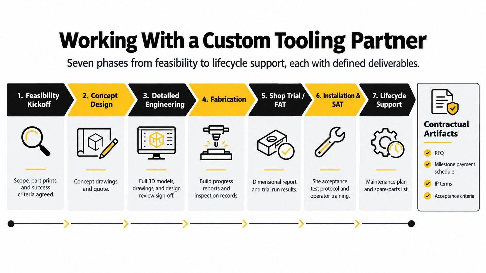
The statement of requirements should include acceptance criteria that someone can test. A shared DFMEA should identify failure modes across the customer's process and the vendor's design. Design-review logs should show decisions and open actions, while validated lines may require an IQ, OQ, and PQ protocol aligned with the site's quality procedures.
Common failures are predictable: vague CAD handover, late DFMEA review, an FAT that tests only an empty cycle, a skipped SAT, and support that disappears after warranty. The spare-parts list should identify recommended reorder levels, lead-time risks, part numbers, and acceptable substitutes where applicable.
Before signing a purchase order, confirm:
- IP ownership: Define who owns custom CAD, drawings, software, and design improvements.
- Revision control: Specify file formats, naming conventions, approval responsibilities, and change-notification rules.
- Change-order pricing: State how scope changes, delays, rework, and customer-caused changes are priced.
- Acceptance testing: Define sample parts, performance criteria, documentation, and remedies for failed acceptance.
- Diagnostics handoff: Require access levels, fault-code documentation, backups, and remote-support responsibilities.
The FDA process-validation guidance reinforces why the partner must support more than fabrication. Production processes need defined parameters, monitoring measures, reference standards, approvals, workmanship criteria, and documented validation or verification where required.
System Engineering & Automation offers manual equipment, custom tooling and fixtures, semi-automatic systems, fully automated equipment, and integrated controls, with support from concept development through drawings, manufacturing, installation, and commissioning. For a production team sizing a tooling project around throughput, flexibility, and GMP-aware documentation, visit System Engineering & Automation to discuss the process, the constraints, and the right level of automation before committing capital.