A production line can look busy and still underperform. Operators may be rechecking parts, maintenance may be responding to unplanned stops, and supervisors may be moving labor between stations to keep orders moving. Each problem seems local, but the causes often interact. A fixture creates variation, variation creates inspection delays, delays create queues, and queues hide the constraint that limits the entire line.
Manufacturing systems engineering gives plant managers and operations leaders a structured way to see those connections. Instead of adding equipment whenever output falls short, teams define the production requirement, map the process, select an appropriate level of automation, and verify that the complete system delivers reliable quality and throughput. That approach is especially valuable for small and mid-sized manufacturers, where every capital decision must balance labor, flexibility, compliance, maintenance, and return on investment.
Table of Contents
- Introduction to Manufacturing Systems Engineering
- Understanding Key Concepts in Manufacturing Systems Engineering
- Exploring Core Methodologies in Manufacturing Systems Engineering
- Integrating Automation with GMP Aware Manufacturing
- Implementation Roadmap for Manufacturing Systems Engineering
- Measuring Benefits and ROI Examples
- Avoiding Common Pitfalls and Choosing the Right Vendor
- Conclusion and Next Steps
Introduction to Manufacturing Systems Engineering
A medical-device workstation offers a familiar example. An operator loads a component into a fixture, performs an assembly, records a result, and sends the part to inspection. The line begins to lose time when the fixture is difficult to load, the inspection step is inconsistent, and a downstream machine stops without giving the operator useful information.
The usual response is fragmented. Production adds another operator, maintenance adjusts the machine, and quality increases inspection. Those actions may relieve pressure temporarily, but they don't answer the central question: how do the people, tooling, equipment, controls, data, and quality procedures work together as one production system?
Manufacturing systems engineering addresses that question. It combines process analysis, mechanical design, electrical controls, automation, human factors, data collection, and validation into one engineering discipline. A practical overview of the broader discipline is available in this guide to what systems engineering means.
Why isolated fixes fail
A faster machine won't improve a line if operators still wait for material. A robot won't solve a process that lacks stable inputs. A new inspection camera may detect defects more consistently, but it can also create a queue if the process can't respond to failures quickly.
The systems view treats the factory like a relay race. Each station has a handoff zone, and the race time depends on more than the speed of the fastest runner. A reliable line needs balanced work, clear interfaces, controlled variation, and feedback when a handoff fails.
Manufacturing systems engineering grew from the same idea. Henry Ford's moving assembly line in 1913 made production more repeatable, while the broader evolution toward coordinated automation later connected machines, controls, and process logic. The lesson remains relevant: optimize the relationship between steps, not just individual equipment.
For a plant manager, the outcome is practical. A structured approach can reveal whether the next improvement should be better tooling, a semi-automatic workstation, a new control strategy, or a fully integrated line. It also creates a defensible path for quality and compliance decisions, so capital spending supports production goals rather than reacting to the loudest problem on the floor.
Understanding Key Concepts in Manufacturing Systems Engineering
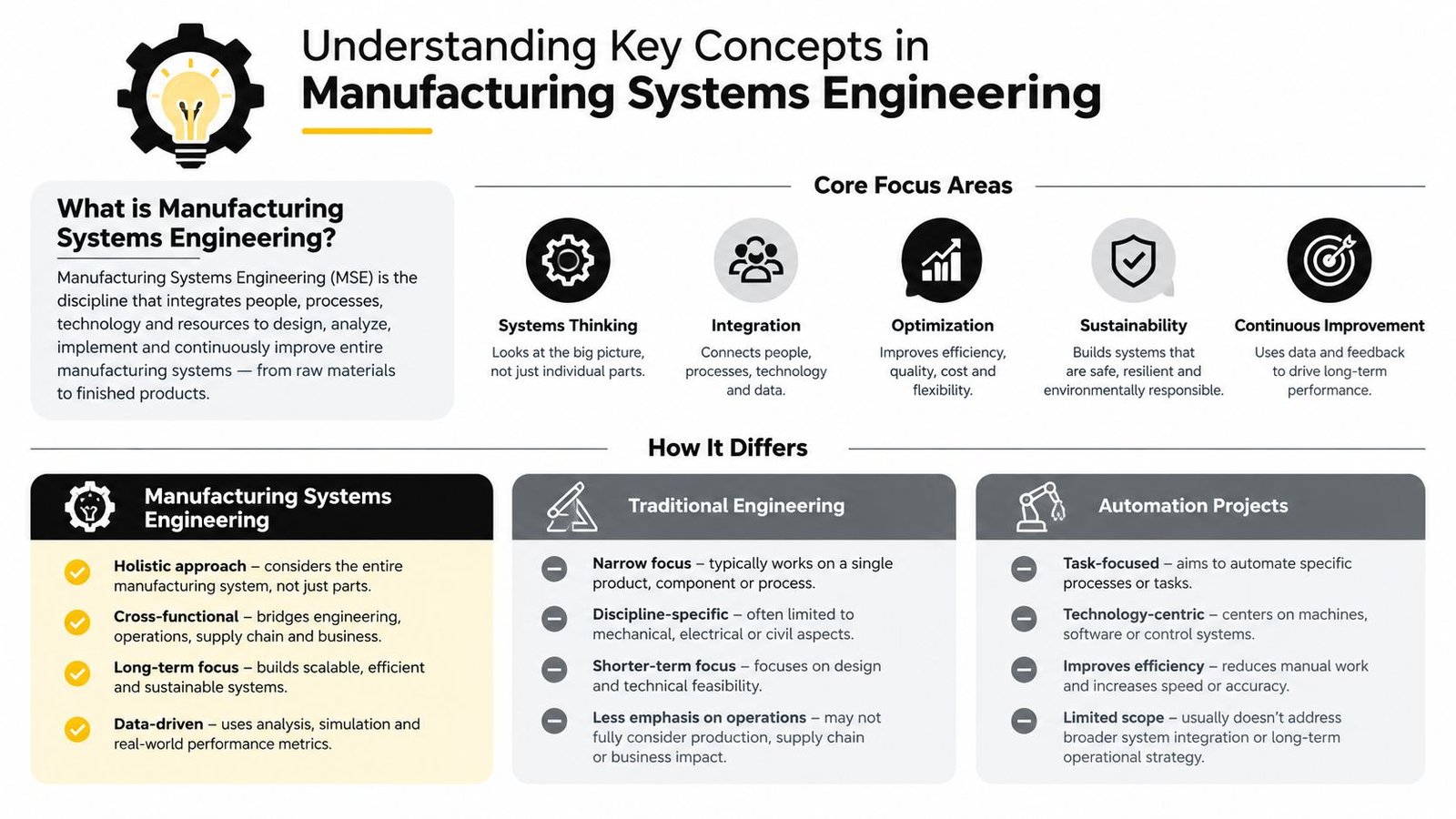
Manufacturing systems engineering treats a factory as an interconnected system. Traditional engineering may focus on a machine, fixture, electrical panel, or building service. An automation project may focus on making a particular operation run without manual intervention. Systems engineering connects those pieces to the complete production requirement.
The distinction matters because a machine can meet its own specification while the line still misses its output, quality, or compliance target. The engineer must understand the product, process sequence, material flow, operator interaction, maintenance needs, controls, data, and quality evidence.
Build the system vocabulary
Start with four questions:
- What must the process achieve? Define the product characteristics, required sequence, acceptance criteria, operator tasks, and production constraints.
- What does each station need from the previous station? Specify material presentation, part orientation, timing, information, and quality status.
- What evidence proves the process worked? Identify measurements, records, alarms, approvals, inspection results, and traceability requirements.
- What happens when something goes wrong? Define safe states, rework routes, fault recovery, escalation, and controlled release of product.
Requirements traceability connects each business or quality need to a design feature and a verification activity. If the requirement says a component must be installed in a defined orientation, the traceability chain should identify the fixture feature that controls orientation, the sensor or inspection method that detects it, and the test that confirms the control works.
Metadata provides the context around process data. A measurement without a part identifier, station identity, recipe, operator record, timestamp, or equipment state may be difficult to interpret later. Strong process controls preserve that context so production and quality teams can distinguish a real process shift from a data-entry or configuration problem.
Think in handoffs, not isolated machines
A production line behaves like a relay race. The upstream station passes more than a part. It passes a part in a known condition, with a known status, at a usable rate. If one station runs faster but creates poorly controlled handoffs, the downstream team inherits the problem.
The historical path supports this systems view. Manufacturing moved from mechanized production toward coordinated automation, including Ford's 1913 moving assembly line and General Motors' first PLC installation in 1958, milestones described in this manufacturing automation history. Modern manufacturing systems engineering applies that same principle with programmable controls, structured requirements, integrated data, and feedback loops.
A useful mental model is:
- Inputs: materials, people, energy, recipes, tooling, and instructions.
- Transformation: assembly, forming, testing, packaging, or another controlled operation.
- Outputs: accepted product, process records, alarms, scrap, and maintenance information.
- Feedback: measurements and decisions that keep the process within its intended state.
Once leaders see those relationships, automation becomes a design choice inside a larger system. The right question isn't “How much can we automate?” It's “Which control, handoff, or source of variation should we improve first?”
Exploring Core Methodologies in Manufacturing Systems Engineering
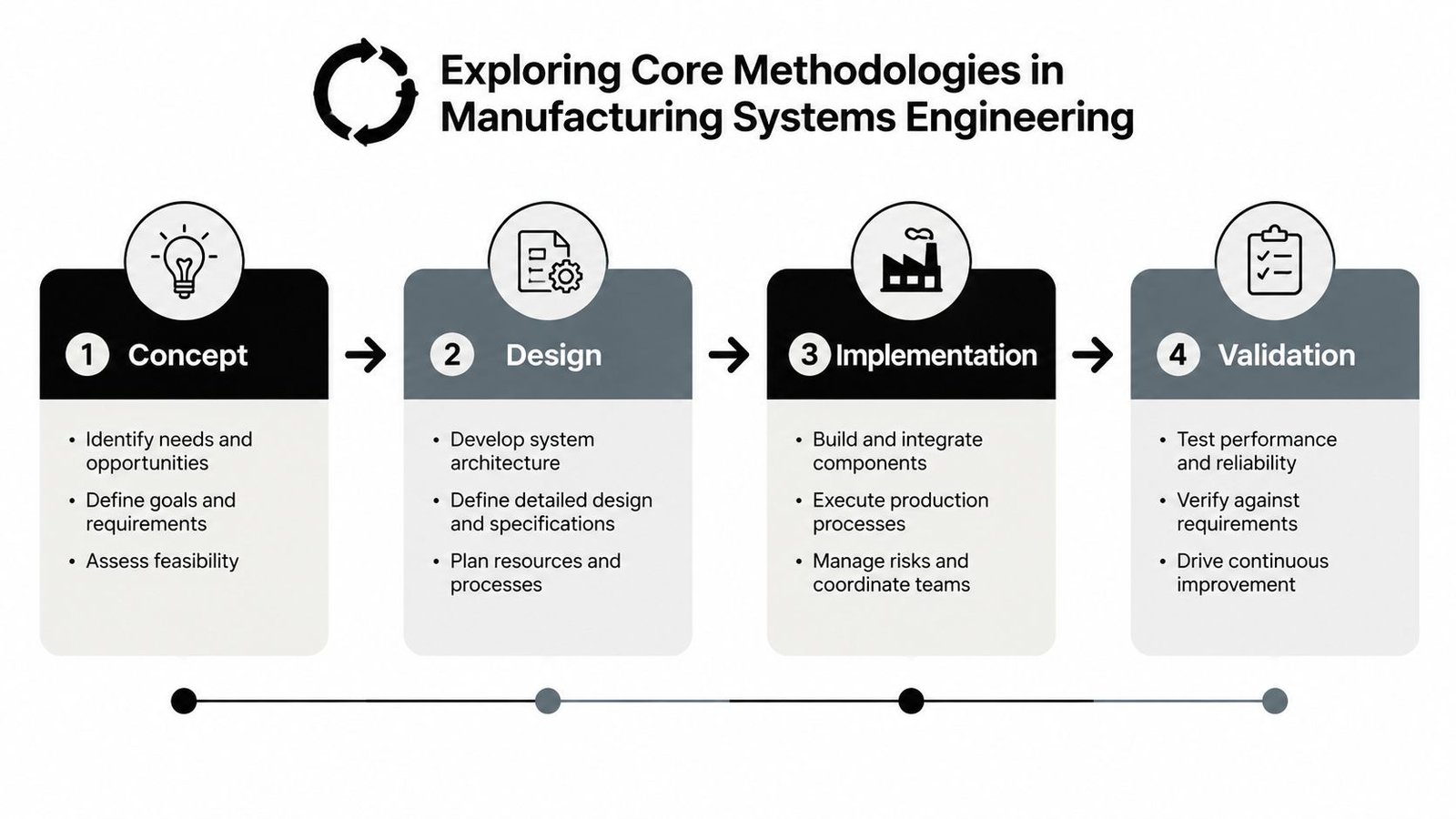
A manufacturing systems project becomes easier to control when the team follows a lifecycle. Four practical phases provide structure: concept, design, implementation, and validation. These phases aren't strictly isolated. Findings during testing may require a design change, and a design decision may expose a missing requirement.
Concept
The concept phase turns a production concern into a defined engineering problem. A team should document the current process, identify losses, observe operator work, review quality records, and establish the desired future state.
A requirements workshop should include operations, production engineering, maintenance, quality, and the people who use the equipment. Ask practical questions:
- Which operation limits the line?
- Which defects originate at the workstation?
- Which tasks create ergonomic or safety concerns?
- What must remain manual because of product variation or changeover needs?
- What records must the system create?
- What happens if the control system, sensor, network, or material supply fails?
The output should be more useful than a general request for “automation.” It might define a guided loading fixture, controlled fastening, automated presence detection, operator prompts, and a record of test results. That description gives the design team a measurable target without prematurely choosing a robot or platform.
Design
The design phase converts requirements into a functional architecture. The team decides which functions belong in tooling, mechanical equipment, PLC logic, human-machine interface screens, vision systems, manufacturing software, or quality procedures.
For example, a station may use a fixture to locate a part, a sensor to confirm presence, a PLC to sequence the operation, and an HMI to guide the operator through recovery. The control strategy should also define permissives, alarm priorities, manual modes, recipe handling, changeover, and safe behavior during faults.
A model-based approach helps teams manage relationships between requirements, functions, physical components, and verification activities. The model-based systems engineering resource provides useful context for organizing those relationships.
Implementation
Implementation includes detailed mechanical and electrical engineering, controls development, fabrication, procurement, assembly, programming, and operator preparation. Keep the design tied to the approved requirements. Uncontrolled changes can alter cleanability, access, cycle behavior, data integrity, or validation scope.
Controls engineers should test sequences using realistic fault conditions, not only the normal production cycle. Maintenance personnel should review access to sensors, actuators, guarding, and wear components before the equipment reaches the plant.
Validation
Validation asks whether the complete process consistently produces the intended result. The team should verify both the equipment and the way people operate it. That includes normal cycles, interruptions, recovery, changeovers, rejected parts, data records, and defined acceptance criteria.
OEE provides a practical production lens. It is calculated as Availability × Performance × Quality, with the components representing downtime, speed, and defect losses, as explained in this OEE calculation guide. A separate benchmark places world-class OEE at about 85% and typical manufacturing performance around 60%, with the difference usually arising from combined losses rather than one isolated fault. The benchmark and its interpretation are discussed in this OEE reference.
The important practice is to measure each loss category separately. A line with strong availability but poor quality needs a different intervention from a line that produces good parts but loses time to stoppages. Automatic data capture and Pareto analysis help the team focus on the dominant constraint.
Integrating Automation with GMP Aware Manufacturing
Regulated production changes the automation decision. A machine isn't compliant because it uses stainless steel, a PLC, robotics, or a clean-looking enclosure. Compliance depends on the complete process, the quality system, documented controls, traceability, and evidence that the process delivers predetermined results.
For a medical-device or pharmaceutical workstation, the design team may need to address cleanability, contamination control, material compatibility, access, software configuration, audit trails, electronic records, operator permissions, maintenance, and change control. Each addition can improve control while also increasing documentation and qualification work.
Match automation to risk
A fully automated line may reduce manual handling, but it can introduce more software, sensors, recipes, interfaces, and failure modes. A semi-automatic station may provide controlled orientation, guided assembly, force monitoring, or automatic testing while leaving a flexible task with a trained operator.
That trade-off should be deliberate. Start by identifying the product and process risks. Then choose the simplest technology that controls the important risk and creates the necessary evidence.
The FDA guidance on computer software assurance emphasizes a risk-based approach for software used in production and quality systems. The practical implication is clear: teams should focus assurance activities on functions that affect product quality, patient safety, process control, or data integrity, rather than treating every software feature as equally critical.
Design for the full lifecycle
A GMP-aware design should answer questions that extend beyond factory acceptance testing:
- Can operators and technicians clean the equipment without hidden product traps?
- Can the process distinguish accepted, rejected, held, and reworked material?
- Can authorized users change recipes, and is that change controlled?
- Does the system preserve the information needed to reconstruct a production event?
- Can maintenance replace a component without creating an uncontrolled process state?
- Do procedures, training, drawings, software versions, and test records remain aligned?
For medical-device and reprocessing workflows, FDA guidance identifies validation evidence involving cleaning, sterilization, and functional performance. It defines process validation as establishing by objective evidence that a process consistently produces results meeting predetermined specifications, as described in this process validation guidance document.
A digital twin can help analyze queueing, station balance, and resource contention before physical changes are made. It doesn't replace qualification or production evidence. It helps the team make better design choices before committing to fabrication.
Practical rule: Treat compliance as a lifecycle design requirement, not a certificate attached to a machine after installation.
Manufacturers can use the good automated manufacturing practices resource to connect automation decisions with documentation, controls, and operational discipline. The right system often isn't the most autonomous one. It's the one that controls the relevant risks without creating a validation burden the organization can't maintain.
Implementation Roadmap for Manufacturing Systems Engineering
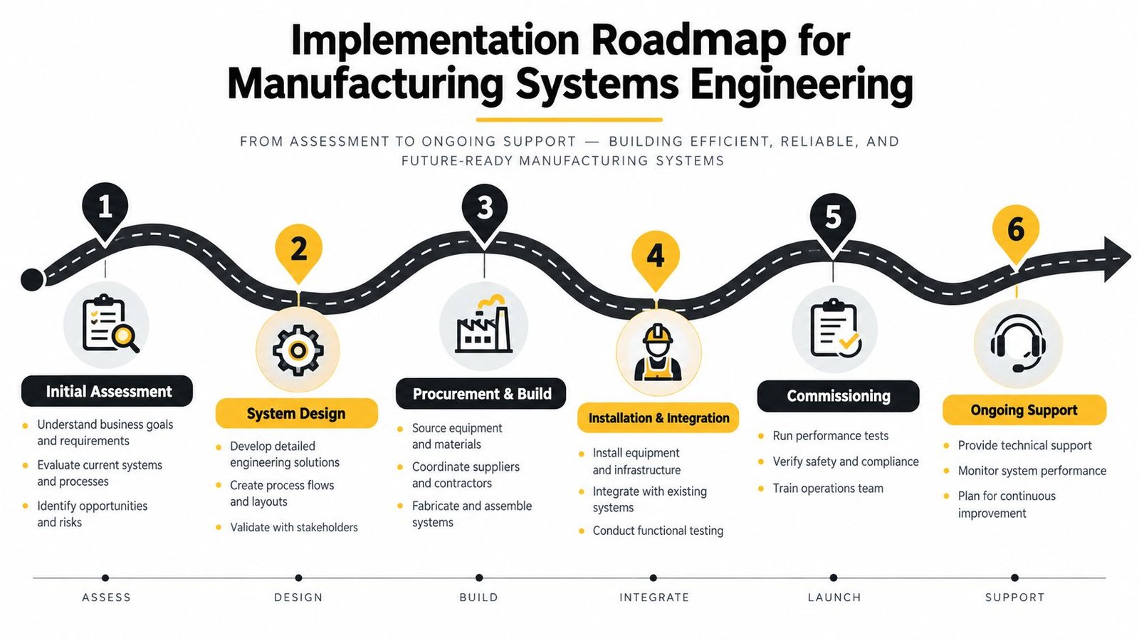
Small and mid-sized manufacturers need a roadmap that connects engineering work to production realities. The sequence below supports a controlled move from manual tooling improvements to semi-automatic equipment or a fully integrated system.
1. Assessment
Begin on the plant floor, not in a vendor presentation. Observe the work, record changeovers and interruptions, review defects and rework, and speak with operators, maintenance technicians, quality personnel, and supervisors.
Create a current-state map that shows material movement, information flow, inspection points, manual touches, and decision points. Identify the constraint and separate symptoms from causes. A slow station may be constrained by loading, material presentation, inspection, or recovery after faults.
Decision checkpoint: Agree on the problem before discussing equipment. The output should include requirements, constraints, risks, baseline measurements, and a prioritized improvement opportunity.
2. Concept design
Develop more than one concept when the automation level is uncertain. One option might improve a manual station with custom tooling and fixtures. Another might add sensors, guided work instructions, or automated testing. A third might integrate conveyors, robotics, controls, and production data.
Compare the options against throughput, flexibility, operator involvement, quality risk, cleanability, maintenance access, training, and validation effort. Small plants often benefit from a staged design that solves the immediate constraint while preserving space and interfaces for later expansion.
Decision checkpoint: Select the concept that fits the production strategy, not merely the concept with the highest theoretical speed.
3. Detailed engineering
Translate the selected concept into engineering documents. Mechanical drawings should define interfaces, tolerances, guarding, access, tooling, and service points. Electrical documents should define panels, devices, safety circuits, wiring, and power requirements. Controls documents should describe sequences, alarms, modes, recipes, permissions, and data handling.
Quality and operations teams should review the design before fabrication. This is the point to catch a difficult cleaning step, an inaccessible sensor, an impractical changeover, or an audit-trail requirement that wasn't included in the original concept.
Design review question: Can the operator, technician, quality reviewer, and validation team each explain how the system will behave during a normal cycle and a failed cycle?
4. Procurement
Procurement involves more than buying components. Confirm supplier lead times, replacement availability, documentation, software ownership, training, and compatibility with existing plant standards. Standard components can simplify maintenance, while specialized components may provide necessary performance or contamination-control characteristics.
Tie purchase decisions to the approved design and change-control process. If a substitute component changes a material, sensor behavior, interface, or software dependency, the team should assess the effect before accepting it.
Decision checkpoint: Release procurement only after critical interfaces, documentation needs, and acceptance criteria are clear.
5. Installation and commissioning
Plan installation around production access, utilities, safety, network connections, material flow, and operator training. Commissioning should progress from individual devices to subsystems, then to complete sequences and integrated operation.
Test the conditions that expose weak designs: missing parts, incorrect orientation, sensor failure, communication loss, rejected product, interrupted cycles, and recovery after a stop. Capture issues in a controlled punch list, assign owners, and verify closure.
A line isn't ready because it completes a demonstration cycle. It's ready when the people responsible for production, maintenance, quality, and safety understand how to operate and support it.
6. Validation and ongoing support
Validation should use approved protocols, defined acceptance criteria, traceable results, and controlled deviations. Regulated plants must connect equipment testing to process evidence, training, procedures, and release decisions.
After launch, monitor the same losses identified during assessment. Review downtime causes, speed losses, quality results, maintenance events, changeover behavior, and operator feedback. Use the information to improve the system without bypassing change control.
For a small or mid-sized plant, ongoing support is part of the business case. A supplier should explain who responds to faults, how software changes are managed, which spare parts are critical, and how future capacity or product changes can be accommodated. A staged implementation protects cash flow and reduces the risk of building an advanced system on unstable process data.
Measuring Benefits and ROI Examples
A sound ROI discussion starts with a baseline. Leaders need to know what the current process consumes and loses before they can judge an improvement. Measure output, accepted product, defects, downtime, speed, labor allocation, changeover behavior, maintenance activity, and the cost of quality work that the current process requires.
OEE provides one practical framework because it separates three different loss types. Availability exposes downtime, Performance exposes speed loss, and Quality exposes defects. The calculation is Availability × Performance × Quality, so a strong result in one category can't hide a serious loss in another.
What the evidence can and can't tell you
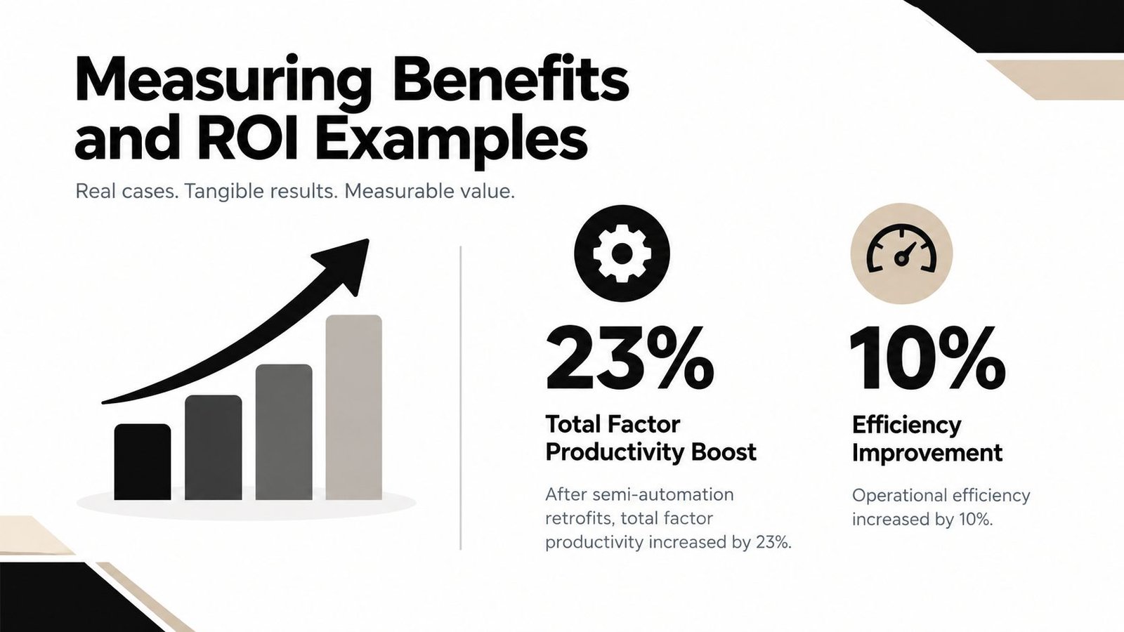
A study covering 22 Thai manufacturing sectors from 2017 to 2020 found that firms using automation had, on average, 23% higher total factor productivity than non-adopters, as reported in the automation and productivity study. That result supports automation as a productivity lever, but it doesn't mean every project will produce the same outcome. The study compares adopters and non-adopters across sectors, while a plant manager must evaluate a specific process, workforce, product mix, and implementation plan.
Digital-twin analysis offers a different type of evidence. One real-factory study reported a minimum 10% throughput improvement after a digital-twin framework identified, diagnosed, and improved bottlenecks, according to the digital-twin bottleneck analysis study. The value comes from revealing queueing and resource contention that may be invisible when teams inspect stations one at a time.
Build the business case around losses
A practical ROI model should connect each proposed feature to a measurable loss:
- Custom tooling: Reduce loading variation, awkward handling, or repeated adjustment.
- Semi-automatic operation: Control the critical step while preserving operator flexibility.
- Automated inspection: Detect defined conditions consistently and route exceptions.
- Integrated controls: Coordinate equipment states, interlocks, alarms, and recovery.
- Digital data capture: Replace incomplete records with usable process history.
- Digital-twin analysis: Test station balance and material flow before physical changes.
Don't count every possible benefit as guaranteed savings. Separate direct benefits, such as reduced scrap or recovered capacity, from indirect benefits, such as easier training, improved traceability, or lower troubleshooting effort. State assumptions clearly and show the sensitivity of the result if production volume, labor availability, or product mix changes.
Why semi-automation can be the rational choice
Full automation can be appropriate when demand, product geometry, process stability, and compliance needs justify its complexity. It can be a poor choice when products change frequently, inputs vary, or the plant lacks the data and maintenance capability needed to support a connected system.
Semi-automation often occupies the useful middle ground. A fixture can control orientation, a sensor can confirm presence, and a controlled actuator can perform the highest-risk operation while the operator handles flexible loading and inspection. This arrangement can improve repeatability without forcing every task into a rigid automated sequence.
Track performance after implementation using the original baseline. Review the dominant OEE loss, not just the headline output. If availability improves but quality worsens, the project needs adjustment. If quality improves but operators wait for material, the next opportunity lies in flow and replenishment.
Measurement principle: A credible ROI case explains which loss changed, how the system captured the evidence, and whether the improvement can be sustained.
Avoiding Common Pitfalls and Choosing the Right Vendor
The most expensive automation mistake is often choosing the wrong level of automation. A team may automate a variable task that still requires human judgment, add software before defining the process, or select a machine that performs well in a demonstration but creates difficult cleaning, changeover, or maintenance work.
Price matters, but it can't be the only comparison. A lower purchase price may conceal engineering exclusions, limited documentation, difficult spare-part sourcing, weak training, or a validation package that doesn't match the plant's quality system.
Avoid over-automation
Start with the constraint and the risk. If a manual workstation loses time because parts arrive poorly oriented, a designed fixture or feeder may solve the issue without a complete robotic cell. If the critical risk involves fastening force or test result integrity, controlled tooling and automatic data capture may matter more than automated loading.
A retrofit makes sense when the existing equipment has sound mechanics, usable interfaces, and sufficient remaining life. New equipment may be more sensible when the current machine lacks guarding, control architecture, cleanability, service access, or the capacity to support the required process.
Use a comparison that forces the trade-offs into view:
| Decision area | Retrofit or tooling upgrade | New integrated system |
|---|---|---|
| Flexibility | Often preserves operator involvement and product adaptability | Can provide coordinated automation, but may require more structured recipes |
| Engineering effort | Focuses on a defined constraint or workstation | Covers broader mechanical, electrical, controls, and data interfaces |
| Compliance impact | May limit the scope of changes when the process remains stable | Can create a broader documentation and qualification workload |
| Maintenance | May use familiar equipment and plant standards | Requires clear training, spares, access, and software support |
| Scale-up | Can provide a staged path | Can support larger integration when requirements are mature |
Evaluate the vendor's working method
Ask each supplier to explain how it will:
- Define requirements: Show how operations, quality, maintenance, and engineering inputs become controlled specifications.
- Manage GMP needs: Explain risk assessment, traceability, software assurance, cleaning considerations, and validation deliverables.
- Test failure modes: Demonstrate how the system handles missing parts, rejected product, sensor faults, interrupted cycles, and recovery.
- Support maintenance: Identify critical spares, diagnostic tools, response arrangements, software ownership, and training.
- Control changes: Describe how substitutions, design revisions, and field modifications are documented and approved.
- Measure results: Agree on baseline data, acceptance criteria, ramp-up expectations, and post-installation review.
System Engineering & Automation is one potential resource for manufacturers seeking consultation, custom tooling, fixtures, semi-automatic systems, integrated controls, or fully automated equipment. Its stated services span preliminary concepts, manufacturing drawings, material sourcing, installation, and commissioning, with ongoing maintenance support for production environments.
Vendor rule: Choose the partner that can explain the process, evidence, and support model as clearly as it explains the equipment.
A responsible supplier won't push maximum automation by default. It will help the plant decide what should remain manual, what needs mechanical control, what benefits from sensors or software, and what requires full integration. That conversation protects both capital and operational trust.
Conclusion and Next Steps
Manufacturing systems engineering gives plant leaders a way to improve production without treating every problem as a machine-purchasing exercise. The strongest projects connect requirements, process flow, tooling, controls, people, data, quality evidence, and long-term support.
For small and mid-sized manufacturers, the practical path often begins with a focused assessment and a better fixture. From there, the plant can add controlled operations, inspection, data capture, or integrated automation as the process becomes more stable. GMP-aware design keeps cleanability, traceability, risk, and validation effort visible from the start.
Begin by documenting one constrained workstation, assembling a cross-functional review team, and defining the losses that matter most. Then schedule a vendor workshop to compare a manual upgrade, a semi-automatic concept, and a fully integrated option against the same production and compliance requirements.
System Engineering & Automation helps manufacturers assess production challenges, design practical tooling and automation, develop engineering documentation, and commission solutions that fit operational and GMP-aware requirements. Visit System Engineering & Automation to discuss your workstation, line upgrade, or integrated manufacturing systems engineering project.