A better-controlled press can use less energy without making fewer parts. In a 2024 comparative test, Netstal reported a 14.6% reduction in machine energy consumption while maintaining productivity. The important purchase decision isn't automatically a new press. It's whether better control can remove waste from the cell you already own.
Table of Contents
- What the Control System Decides on Every Shot
- The Five Layers Inside a Molding Controller
- Closed-Loop Signals That Protect Part Quality
- Energy Savings That Keep Cycle Time and Quality
- Retrofit Controls Versus a New OEM System
- Plant Data Quality Records and Device Rules
- Commissioning a Control Upgrade Step by Step
What the Control System Decides on Every Shot
An injection molding machine control system acts as the conductor of the molding cell, but a new screen doesn't fix a weak process. Plastics Engineering reported in 2024 that process monitoring and parameter visibility can typically reduce molding energy consumption by 7% to 13%, based on Kern IoP data. Visibility helps only when engineers use it to change how the machine operates.
Consider a plant running older hydraulic presses beside a newer electric cell. The older machines still clamp reliably, but operators spend too long restoring setups, suspect parts accumulate beside the conveyor, and pumps keep running hard during low-demand periods. Replacing the entire machine may solve those problems, but it may also replace serviceable mechanics unnecessarily.
The controller sequences mold closing, injection, packing, holding, cooling, screw recovery, opening, and ejection. Some operations overlap, so it must coordinate permissions and timing rather than just advance through a timer list. It also exchanges ready, busy, complete, and fault signals with robots and auxiliary equipment.
Start with the production constraint
Before specifying hardware, identify what prevents the cell from producing more acceptable parts:
- Unstable filling: Determine whether actual velocity and pressure follow the commanded profiles.
- Slow changeovers: Check whether operators restore complete, approved recipes or rebuild settings manually.
- Interrupted handling: Identify missing handshakes between the press, robot, conveyor, and inspection station.
- Unnecessary power demand: Separate productive actuator work from unloaded running and standby consumption.
These are different problems. They don't justify the same upgrade.
Practical rule: Judge the controller by acceptable parts leaving the cell, not by how modern its interface looks.
Operations leaders need a clear boundary between the layers that execute the shot, the upgrades that preserve a sound machine, and the records that demonstrate controlled production. Throughput, labor requirements, and quality should determine that boundary. A faster nominal cycle isn't an improvement if operators must stop more often to sort parts.
The Five Layers Inside a Molding Controller
Control layers and the job each one owns
| Layer | What it commands | Typical signals | Production job |
|---|---|---|---|
| PLC or industrial PC | Sequence, interlocks, recipes, alarms | Digital I/O, cycle states, safety inputs | Repeatable shot order and safe stops |
| Motion control | Screw speed, pressure transfer, clamp, eject | Position, velocity, pressure or torque | Fill consistency and cycle time |
| Sensors | Feedback for temperature, pressure, position, strain | Thermocouples, transducers, encoders, tie-bar strain | Early detection of drift and short shots |
| HMI | Setpoints, curves, alarms, operator prompts | Recipe screens, trend plots, fault text | Faster setup and fewer undocumented tweaks |
| Process software | Logs, recipes, SPC hooks, peripheral links | Shot records, energy by stage, robot handshakes | Traceability and plant-wide visibility |
Treat these as cooperating layers, not separate boxes that must each be purchased. A machine platform may combine sequence execution, motion tasks, and data storage in the same hardware. What matters is clear ownership of commands, feedback, and fault responses.
A kitchen line is a useful analogy. The PLC is the ticket rail that establishes order, motion control is the cooks' hands, sensors provide the checks, the HMI is the pass window, and process software preserves the order history. A better pass window won't correct an incorrect sequence or an unreliable measurement.
Sequence and motion have different responsibilities
The PLC or industrial PC decides whether an operation is permitted and what happens next. For example, ejection shouldn't begin until the mold reaches its permitted position and the handling equipment is clear. Our explanation of PLC programming basics provides useful context for distinguishing sequence logic from operator commands.
Motion control determines how the actuator follows its command. Screw acceleration, velocity tracking, pressure transfer, clamp movement, and ejection need appropriate response, not just an on signal. On hydraulic equipment, that means coordinated valve and pump behavior; on electric equipment, it means coordinated servo motion.
Safety-related functions require an appropriately designed safety architecture. An ordinary PLC receiving a safety status signal doesn't make its standard application program a safety controller.
Feedback and interfaces need defined limits
Sensors provide measurements, but the engineering specification must identify what each measurement represents. A barrel thermocouple doesn't measure mold temperature, and hydraulic pressure isn't a direct measurement of polymer pressure inside the cavity. Check sensor location, scaling, calibration, and failure behavior before using a signal for control.
The HMI should expose approved settings, actual curves, actionable alarms, and permitted adjustments. Separate operator access from engineering access, and prevent recipe screens from concealing changes made elsewhere in the program.
Process software should preserve context: which recipe ran, which material and mold were identified, what the machine measured, and what disposition followed. Statistical process control, or SPC, is useful only when those records describe comparable production conditions.
Automation doesn't automatically mean robotics. PLC logic, fixtures, conveyors, and operator-assisted stations can remove the actual bottleneck without adding robot tending. If a proposed layer can't identify the signal it owns and the production failure it addresses, remove it from the specification.
Closed-Loop Signals That Protect Part Quality
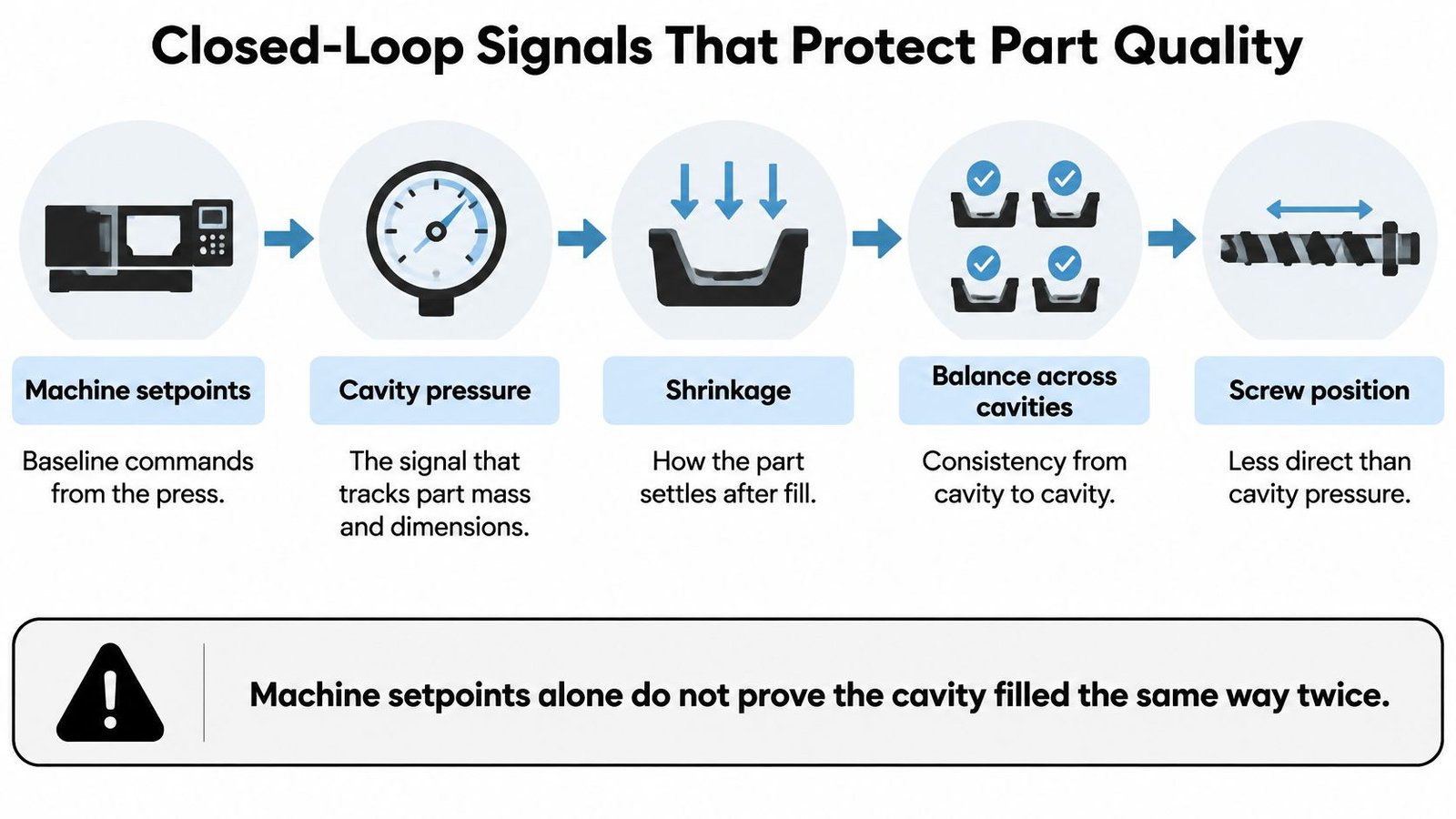
Cavity-pressure feedback is a stronger starting point for part-quality control than assuming identical machine setpoints produce identical cavities. A Polymers study available through PubMed Central connects cavity pressure with part mass, dimensional accuracy, shrinkage, and geometric uniformity, and examines its use in controlling velocity-to-pressure transfer and packing.
Use the pressure signal to understand what happened inside the tool, then decide which interventions are justified. The relationship between the commands and the molded result is illustrated below.
Build alarms around the curve
Start with stable, accepted production and synchronize cavity pressure with screw position and injection velocity. Confirm the acquisition system captures the transfer event and packing behavior clearly enough to distinguish a real deviation from measurement noise.
Don't stop at a peak-pressure alarm. Define a usable set of curve features:
- Arrival time: Detect changes in when melt reaches the sensor.
- Pressure integral: Track the accumulated pressure history over a defined interval.
- End-of-pack pressure: Identify changes near the end of the packing stage.
- Cavity comparison: Flag differences between instrumented cavities rather than trusting the machine-level average.
Use these features to investigate short shots, viscosity shifts, gate-freeze changes, and cavity imbalance. Establish limits from acceptable production and deliberate process challenges, not from the widest range the controller can display.
Pressure control also has a boundary: mold-temperature stability matters. When thermal conditions change, maintaining the pressure curve alone may not preserve dimensions. Include temperature compensation or a coordinated pressure-temperature strategy where qualification shows it's needed.
The accompanying process video provides additional visual context for the molding operation.
Use indirect signals conservatively
When cavity instrumentation isn't practical, consider nozzle pressure, tie-bar strain, or mold separation. A Polymers review of indirect sensing and adaptive control describes these approaches while identifying material dependency, mold complexity, and cross-platform transferability as unresolved challenges.
Establish a golden-cycle baseline for the specific machine, mold, and material. Correlate indirect measurements with inspected parts before assigning reject limits, and don't copy limits from another press because the recipe looks similar.
Separate alarm-only monitoring from closed-loop intervention. Monitoring can warn an operator or segregate a suspect shot; intervention changes the process. For medical components, retain human approval until the correction logic, permitted adjustment range, records, and change-control procedure have been validated.
Energy Savings That Keep Cycle Time and Quality
Energy performance belongs to the application, not just the machine nameplate. Polymer behavior, tool thermal design, screw geometry, actuator hardware, and control logic all influence consumption, as Plastics Engineering explains in its discussion of application-specific energy assessment. A controller dashboard cannot isolate those effects unless measurements retain process context.
The factors below belong in the baseline, not in a footnote after commissioning.
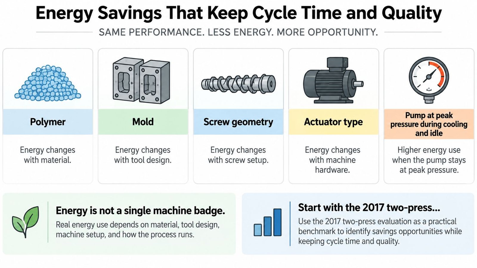
Read the benchmarks at their actual scope
In a 2017 study of two injection molding machines, the Energy Efficiency paper reported a 41.3% electricity reduction from a variable-frequency drive, followed by a further 12.2% saving from parameter optimization. The study's combined intervention also produced the annual savings and payback shown below.
Reported energy results for control-driven savings
| Measure | Reported result | Context |
|---|---|---|
| Variable-frequency drive alone, 2017 study | 41.3% electricity reduction | Two injection molding machines |
| Parameter optimization, 2017 study | 12.2% additional electricity saving | Coordinated melt temperature, mold temperature, and clamping force |
| Combined intervention, 2017 study | 107,200.5 kWh and 55,851.5 kg CO2 saved per year | Payback under four months |
| Process monitoring and parameter visibility, 2024 Plastics Engineering | 7% to 13% typical energy reduction | Based on Kern IoP data |
| Adaptive system-pressure control, 2024 Netstal test | 14.6% machine energy reduction | Productivity maintained |
The study examined melt temperatures from 310.0 to 350.0 °C, mold temperatures from 110.0 to 130.0 °C, and clamping forces from 120 to 160 tons, with a reported optimum of 330.0 °C, 120.0 °C, and 140 tons, respectively. Those are study conditions, not settings to copy into another process.
Don't add the reported percentages together or apply them to a plant budget as guaranteed savings. Different interventions act on different losses, and their benefits can overlap.
Measure complete cycles and accepted output
Research on hydraulic injection-molding control examines the trade-off between hydraulic response and energy consumption across pump and pressure-control strategies. Specify hydraulic power against instantaneous demand rather than holding peak injection capability throughout cooling and idle operation.
Coordinate servo-pump speed, pump displacement where applicable, pressure compensation, and screw-velocity tuning. Poor coordination can produce oscillation, delayed filling, or inconsistent transfer.
Measure electrical input with a suitable power meter synchronized to machine cycle states. Allocate consumption to plasticizing, injection, packing, cooling, and idle, accounting for overlapping operations rather than double-counting them.
Lower power draw isn't proof of improvement if the cell takes longer or produces more rejects.
Use energy per acceptable part: total measured energy divided by accepted output over the same production interval. Keep material, shot size, quality limits, and production conditions comparable, and report cycle time and scrap beside the energy result.
Retrofit Controls Versus a New OEM System
Keep sound mechanics when control obsolescence is the constraint. Replace the machine when its mechanical capability, safety architecture, or process envelope prevents the required result. A controller can't restore a worn screw or create clamp capability the press doesn't have.
The technology gap can still be substantial. KraussMaffei's control-system history documents the transition from relay contacts to electronic control in the late 1970s and the introduction of MC1 in 1980. Modernization is therefore more than replacing pushbuttons with a touchscreen: it can change sequencing, parameter management, diagnostics, and equipment coordination.
Retrofit, new OEM controls, or a staged upgrade
| Path | Best when | What changes | Disruption | Main risk |
|---|---|---|---|---|
| Control retrofit | Mechanics and safety hardware are still sound | PLC or IPC, drives, sensors, HMI, shot logging | Days to a few weeks on one press, as a planning scenario rather than a quoted schedule | Untuned loops or incomplete safety recertification |
| New OEM system | Clamp, screw, or safety category is the limit | New machine and native controller | Longest lead time and highest capital for a comparable scope | Paying for iron the plant did not need |
| Staged semi-automatic | Budget or volume does not justify a full cell | Panel and sensors now, robot or tending later | Shortest first outage when the initial scope is limited | Stopping after the screen and never closing the loop |
Treat disruption rankings as scope-dependent planning judgments. A retrofit with undocumented wiring and custom hydraulic interfaces can require more investigation than an apparently larger replacement project.
Confirm the decision before purchasing
Use these gates to turn an attractive proposal into an executable project:
- Mechanical condition and safety: Inspect the clamp, screw, hydraulics, guarding, and protective functions. Identify the applicable safety assessment and conformity work before altering control responsibilities.
- Signal access: Establish whether pressure and power measurements can be added through supported interfaces or external acquisition without replacing the machine CPU.
- Recipe and permissions: List the settings that must transfer together, the users permitted to change them, and the record required after each change.
- Commissioning access: Agree on production windows, mold availability, material, operators, quality support, and recovery arrangements.
- Acceptance evidence: Put acceptable output, energy measurement, setup behavior, and fault recovery into the acceptance specification.
A targeted legacy-system automation retrofit makes sense when it removes a defined constraint while preserving useful equipment. It doesn't make sense when obsolete controls are only the most visible symptom of an exhausted machine.
Price the integration work, not just the panel
Include drawings, software access, backups, sensor installation, safety engineering, loop tuning, training, and qualification in the comparison. Add expected production interruption and the cost of maintaining temporary stock.
A retrofit wins when it preserves a useful asset and removes the actual constraint, not merely when its hardware quotation is smaller.
Require baseline and post-upgrade runs on the same part. If a servo-pump proposal cannot explain how filling response will be checked after tuning, its energy estimate isn't enough to support the purchase.
Plant Data Quality Records and Device Rules
A control upgrade that never leaves the press is only half integrated. Give production and quality teams a usable record, not an export containing hundreds of unexplained tags. The minimum handoff should identify the shot, its approved setup, relevant deviations, and the resulting disposition.
The checklist below identifies the core information that must remain understandable outside the HMI.
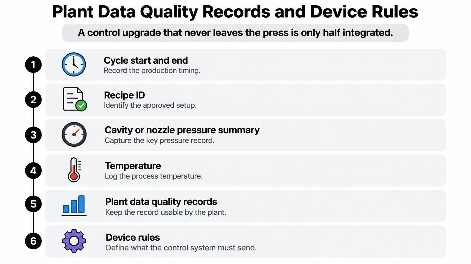
Make the record usable before expanding it
Capture cycle start and end, recipe ID and revision, pressure summaries, temperature deviations, reject reason, and energy by stage. Preserve consistent clocks, units, part numbers, mold identifiers, and cavity identifiers where applicable. A shot log exported on a controlled schedule can be a practical starting point without immediately installing a manufacturing execution system.
Define how the system handles missing records, full storage, interrupted exports, and restored connections. Missing evidence must not become an accepted shot. A telemetry and process-controls architecture should specify the data destination and failure response as clearly as the normal transfer.
Connect automation to the quality system
FDA's software-validation guidance discusses production software validation under the legacy requirement in 21 CFR §820.70(i), including documented protocols and results. Treat that citation as the guidance's regulatory context, not a substitute for checking the currently applicable requirements.
For a present-day device project, align the controller's intended use and validation approach with the manufacturer's quality system and current 21 CFR Part 820. Specify and verify molding parameters, alarms, recipes, data collection, and automatic accept-or-hold decisions rather than treating them as informal machine adjustments.
FDA's process-validation guidance defines validation around objective evidence of consistent conformance to predetermined specifications. Translate that principle into monitored process parameters, qualified personnel, documented results, and assessment of changes that may require revalidation.
Include these reliability checks in the specification:
- Communication failure: Define watchdog behavior and an engineered safe state appropriate to the hazard.
- Configuration recovery: Preserve approved program, recipe, and parameter backups with a tested restoration procedure.
- Maintainability: Provide labeled panels, current drawings, accessible diagnostics, and appropriate spare I/O.
- Change control: Record authorized modifications and prevent opaque auto-tuning from changing qualified settings without review.
Traceability isn't a separate reporting feature. It connects the approved process, the machine's actual behavior, and the decision to release or hold production.
Commissioning a Control Upgrade Step by Step
Commissioning should produce evidence that the modified cell works, not just demonstrate that its outputs turn on. Assign ownership across operations, maintenance, process engineering, and quality before the outage. Each stage needs an acceptance condition and a defined response if it fails.
Establish and prove the operating window
Baseline the cell. Run a representative mold with the current approved setup. Record scrap, cycle time, stage-level energy, accepted output, and relevant quality measurements, retaining material and environmental context.
Freeze the reference. Save the golden cycle, recipe revision, sensor configuration, and alarm list. Include arrival-time, pressure-integral, and end-of-pack limits where those signals are available and qualified.
Complete the panel specification. Identify the PLC or industrial PC, drives, sensors, HMI, logging functions, and peripheral interfaces. Document watchdogs, communication-loss behavior, backup requirements, and safety responsibilities before wiring begins.
Commission in controlled stages. Prove sequencing and logging first, establish trustworthy cavity or nozzle measurements next, and enable automatic adjustments last. Keep a human approval gate until the permitted corrections have supporting evidence.
Challenge the modified cell. Run the same part under comparable conditions and compare accepted output with the baseline. Investigate fill delays or oscillation before accepting servo-pump tuning, and test sensor faults, interrupted handshakes, restart behavior, and suspect-part segregation.
Release and maintain the improvement
Complete the required quality release. For finished-device production, execute the approved validation protocol, document results, resolve deviations, and authorize release under the applicable quality procedures. Don't release the cell solely because it completed a demonstration run.
Schedule a one-year review. Treat this as a recommended maintenance and process-review interval, not a guaranteed service commitment. Bring the baseline, alarm list, validation protocol, maintenance history, and the same part-quality limits to the review.
At System Engineering & Automation, we provide integrated control panels for automatic and semi-automatic systems and upgrade legacy equipment with modern controls and automation. We also design production systems that combine robotics, sensors, control systems, and software, with integration planned to enhance existing equipment rather than unnecessarily disrupt it.
System Engineering & Automation offers integrated controls and legacy-equipment upgrades for manufacturers improving molding-cell production. Visit System Engineering & Automation to discuss your cell's constraint, and bring your cycle baseline, alarm list, and quality requirements so we can help define an appropriate upgrade scope.