You might be dealing with this right now. A line runs well when the most experienced operator is on shift, then drifts when a different operator takes over. A simple machine stop turns into an hour of troubleshooting. Quality issues show up in batches, not because the process is impossible to control, but because the control method depends too much on manual timing, relay logic, or tribal knowledge.
That's where PLC programming basics matter. Not as an academic topic, and not as a software exercise. They matter because a well-programmed PLC gives a machine the same decision-making process every cycle, every shift, and every production run. For manufacturers looking for practical ways to optimize production and services, that consistency is what turns automation from a capital expense into an operating advantage.
Most beginner content stops at syntax. It shows how to place contacts and coils on a screen. That's useful, but it doesn't solve the harder problem. Production equipment has to handle missed parts, bad signals, startup conditions, stops in mid-cycle, operator resets, and abnormal states without becoming unpredictable. The primary value in learning PLC programming basics is understanding how to build control logic that stays deterministic when the process gets messy.
Table of Contents
- What Is PLC Programming and Why It Matters for Your Production Line
- Understanding the Core Components of a PLC System
- How a PLC Thinks The Repetitive Scan Cycle Explained
- Choosing the Right Tool A Look at PLC Programming Languages
- Practical Examples of Basic PLC Logic
- From Simulation to Production Safety and GMP Considerations
- Your Next Steps in Manufacturing Automation
What Is PLC Programming and Why It Matters for Your Production Line
PLC programming is the logic that tells a machine when to start, stop, clamp, count, reject, alarm, or wait. On the plant floor, that makes the PLC the operational brain of the equipment. If the logic is solid, production becomes repeatable. If the logic is weak, the machine may still run, but it won't run reliably.
That distinction matters to managers because poor control logic creates business problems fast. You see it in inconsistent cycle behavior, nuisance faults, slow changeovers, and maintenance teams spending too much time tracing signals instead of fixing root causes. Manual workarounds often keep output moving for a while, but they also hide process weaknesses and make quality harder to defend.
Reliability shows up as throughput and quality
A PLC doesn't get distracted, skip a step, or forget a sequence. It follows programmed logic exactly. That's why even basic automation often stabilizes output more effectively than a collection of relays, timers, and operator judgment calls.
When a line is controlled by clear, repeatable logic, several practical gains follow:
- Fewer timing-related errors: The machine performs the same sequence in the same order.
- Less scrap from inconsistent handling: Outputs respond to defined conditions instead of operator interpretation.
- Faster troubleshooting: Technicians can monitor machine states rather than guessing what happened.
- Safer operation: Interlocks can block hazardous actions before they occur.
Practical rule: Don't judge a PLC program by whether the machine cycles once. Judge it by how it behaves during stops, restarts, faults, and operator mistakes.
Good automation solves process problems, not just control problems
A lot of equipment gets automated too directly. Someone takes a manual sequence and copies it into ladder logic without asking whether the process itself is well-defined. That approach usually underdelivers. The better approach is to use PLC programming to remove ambiguity from the process.
For a manufacturing manager, that means the best PLC projects aren't just “machine upgrades.” They're production tools. They help standardize cycle timing, enforce sequencing, support quality checks, and reduce dependence on the one operator who knows the workaround.
That's the promise behind PLC programming basics. You're not learning code for its own sake. You're learning how automated decisions improve uptime, reduce waste, and support the production system your team has to live with every day.
Understanding the Core Components of a PLC System
Before anyone reviews ladder logic or sequence steps, it helps to understand what the hardware is doing. A PLC system is straightforward by nature. It takes information in, processes that information in the CPU, and sends commands back out to the machine.
That's why the simplest mental model is a nervous system. The CPU is the brain. Input modules are the senses. Output modules are the muscles.
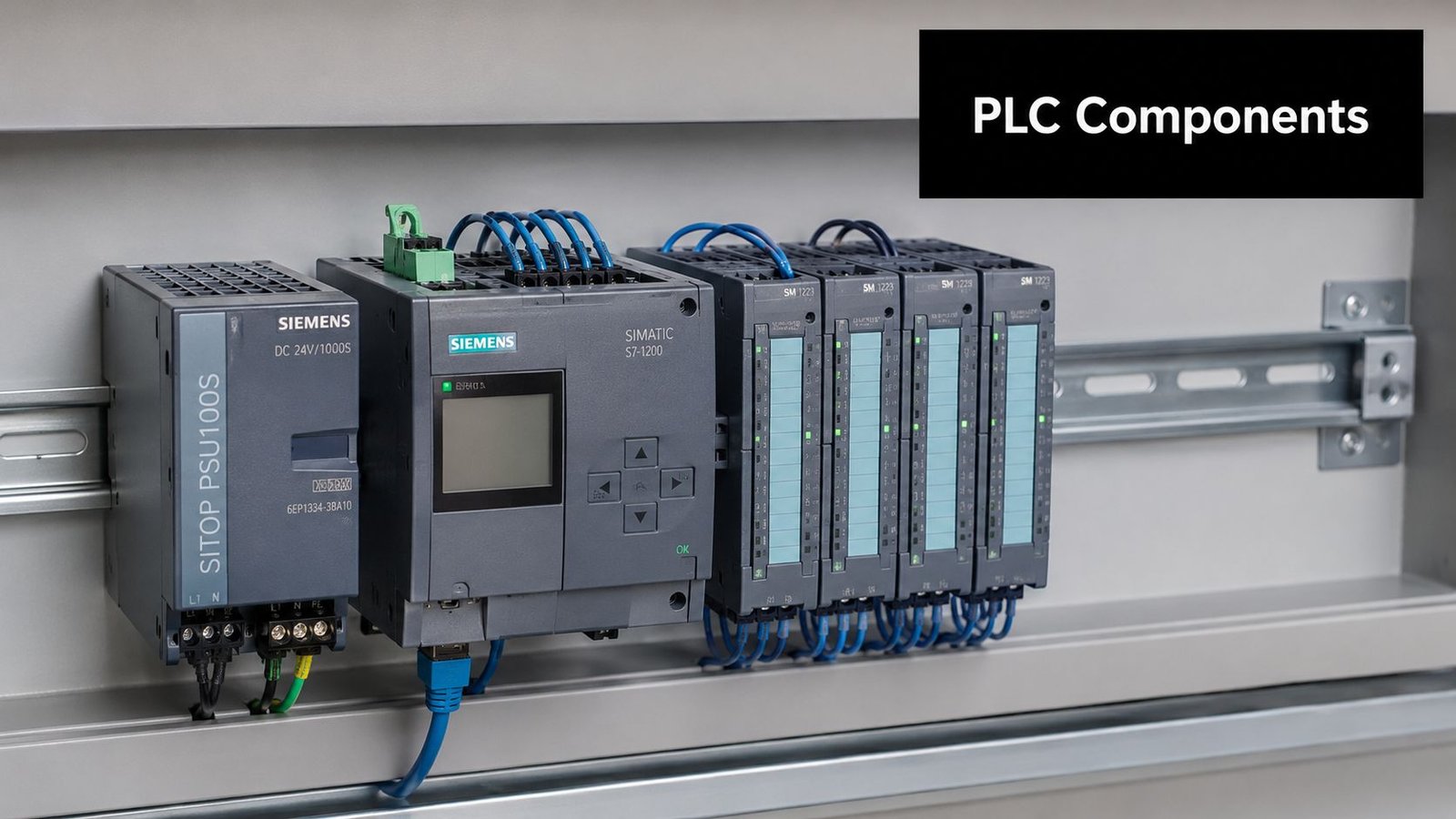
The CPU inputs and outputs
The CPU executes the control program and decides what the machine should do next. It doesn't directly interact with the physical world. It depends on inputs to report machine conditions and outputs to command physical devices.
Inputs usually include devices such as:
- Pushbuttons and selector switches: Operator requests like Start, Stop, Reset, or Auto mode
- Sensors: Photoeyes, prox switches, pressure switches, and level devices
- Safety-related status signals: Guard door status, interlock feedback, or machine-ready conditions
Outputs then act on those decisions:
- Motor starters and drives: Start a conveyor, index a table, or move a feeder
- Solenoids and valves: Extend a cylinder, release air, or switch fluid flow
- Stack lights and alarms: Tell operators when the line is running, waiting, or faulted
For operations teams, this matters because every production problem eventually comes back to one of these points. Either the PLC never saw the input it expected, the CPU logic blocked the next step, or the output didn't create the action the machine needed.
Why tag names change maintenance work
Older PLC programs often rely on address-based naming that only makes sense if you already know the hardware map. Modern systems are easier to live with because they use descriptive tags. According to Control Engineering's discussion of PLC programming in discrete manufacturing, modern PLCs operating in industrial environments utilize tag-based memory systems over traditional address-based conventions, reducing program development time by approximately 40% and minimizing I/O mapping errors.
That improvement is practical, not cosmetic. A tag like Station3_Clamp_Prox tells maintenance exactly what device the program is watching. A raw address does not.
A readable PLC program lowers the cost of ownership long after commissioning ends.
For managers planning upgrades, this is one of the easiest places to justify better engineering discipline. Clean tags, clear device names, and organized I/O structures make troubleshooting faster, training easier, and future expansion less risky. That's especially important in semi-automated systems where operators, maintenance, and engineering all need to understand the same machine behavior.
If you're evaluating broader automation control systems for manufacturing operations, ask to see how tags, alarms, and I/O naming are handled. It has a direct impact on service time and line support.
How a PLC Thinks The Repetitive Scan Cycle Explained
A PLC doesn't think like a desktop computer waiting for someone to click a command. It runs in a loop. Constantly. That loop is what makes industrial control predictable.
The three phases that drive every machine cycle
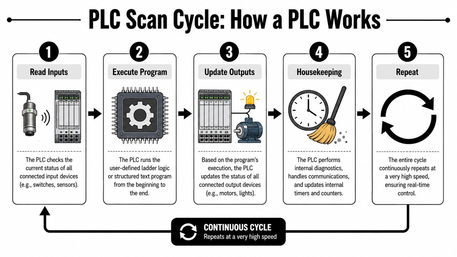
According to PLC Paramedics' explanation of PLC basics, every PLC program operates through a scan cycle with three mandatory phases: Input Scan, Program Execution, and Output Scan. Modern high-speed PLCs can complete that full cycle in under 10 milliseconds.
That sequence shapes how every machine behaves.
Input Scan
The PLC reads the status of connected inputs such as sensors, switches, and buttons. It stores those values as a snapshot, which means the program works from a consistent picture of the machine state.Program Execution
The CPU solves the logic using that snapshot. It checks conditions, runs timers, updates counters, and determines what outputs should turn on or off.Output Scan
The PLC writes the calculated results to the physical outputs. That's when motors, valves, lights, and relays respond.
The infographic above includes housekeeping and repeat steps for visualization, and those are useful to understand operationally. But the core control action always comes back to those three mandatory phases.
What this means on the plant floor
The scan cycle explains several issues that confuse people new to PLC programming basics.
First, inputs aren't evaluated as a stream of random live events. They are read, stored, then used. That's why a sequence can be deterministic if the logic is written properly.
Second, timers and counters aren't “extra features.” They're basic tools for production control. They handle dwell times, reject counts, part spacing, handshake timing, and synchronization between stations.
Third, troubleshooting gets easier when you think in scan order. If a cylinder didn't extend, ask:
- Was the permissive input present during the scan
- Did the logic solve true
- Did the output command energize
- Did the field device respond
If you understand the scan cycle, you stop blaming the PLC for vague problems and start isolating real ones.
That's also why deterministic programming matters more than flashy code. The PLC will do exactly what the scan tells it to do, over and over. If the sequence is incomplete or ambiguous, the machine will repeat that weakness just as consistently as it repeats good logic.
Choosing the Right Tool A Look at PLC Programming Languages
Language choice affects more than programmer preference. It changes how quickly your team can troubleshoot, how clearly a sequence can be reviewed, and how maintainable the machine will be after startup.
Why IEC 61131-3 matters
PLC programming fundamentals are built around the IEC 61131-3 standard. As summarized by Wevolver's guide to PLC programming, the standard defines five programming languages used globally: Ladder Diagram (LD), Structured Text (ST), Function Block Diagram (FBD), Instruction List (IL), and Sequential Function Chart (SFC). The same source notes that 90% of PLC-based control systems utilize a combination of at least two of these defined languages.
That's important because good control systems rarely come from forcing one language to do everything. They come from matching the language to the task.
A practical comparison of LD ST and FBD
In North American plants, Ladder Diagram remains the most widely used language for discrete control applications, accounting for over 70% according to AMD's overview of PLC programming fundamentals. That lines up with what works on real factory floors. Ladder is visual, familiar to electricians and maintenance technicians, and easy for operations leaders to review.
Structured Text and Function Block Diagram both have clear strengths too.
| Language | Best For | Key Advantage |
|---|---|---|
| Ladder Diagram (LD) | Discrete machine logic, interlocks, start/stop circuits | Easy for technicians and managers to read against electrical intent |
| Structured Text (ST) | Complex calculations, data handling, recipes, conditional routines | Compact code for logic that becomes clumsy in rung form |
| Function Block Diagram (FBD) | Process control, analog relationships, reusable logic blocks | Visual flow that works well for continuous functions |
A few practical trade-offs matter more than theory:
- Ladder Diagram works best when maintenance owns the machine after launch. If your technicians troubleshoot from live logic screens, ladder usually lowers support friction.
- Structured Text is better for dense algorithmic work. Formula-heavy routines, string handling, and advanced data manipulation are often cleaner in ST than in a page full of nested branches.
- Function Block Diagram fits process-style relationships. If you're linking control blocks, analog values, and reusable behaviors, FBD can make the logic easier to follow.
Selection advice: Choose the language your plant can maintain, not just the language your programmer prefers.
The strongest approach is often mixed. Use Ladder Diagram for machine states, permissives, and operator-facing logic. Use Structured Text where the math or data handling justifies it. Use Function Block Diagram where visual process relationships add clarity. That gives you a program the floor can support without giving up engineering efficiency.
Practical Examples of Basic PLC Logic
The fastest way to make PLC programming basics tangible is to look at a circuit most manufacturers recognize. A motor start/stop rung is simple, but it contains the same logic patterns used in much larger machines.
This kind of rung shows how an operator request becomes a maintained machine action, and how the logic stops safely when a stop condition occurs.
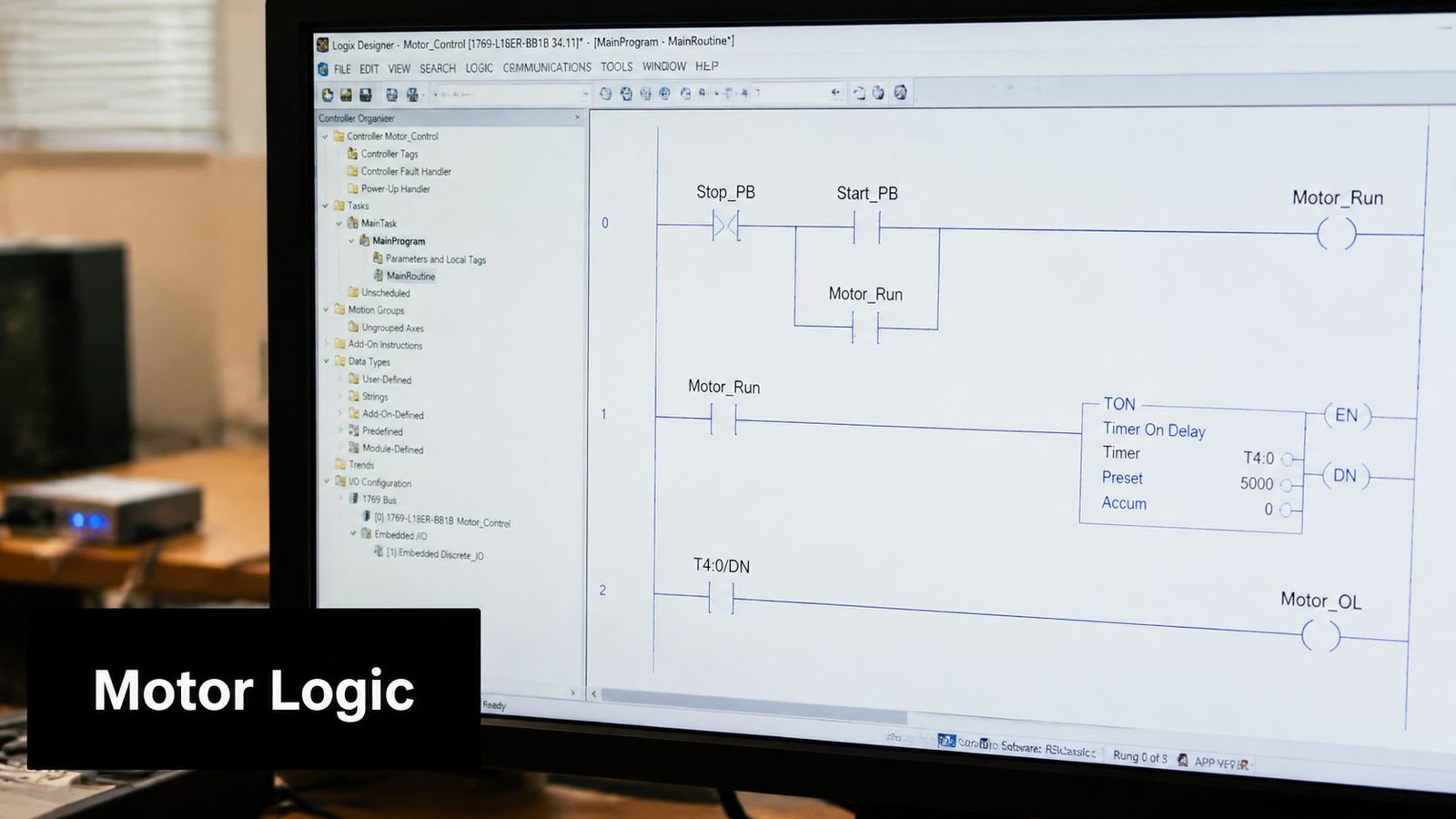
A simple motor start stop rung
A typical ladder rung looks like this in plain text:
| Element | Type | Function |
|---|---|---|
| Stop_PB | Normally closed contact | Allows the rung to run unless Stop is pressed |
| Start_PB | Normally open contact | Starts the motor when pressed |
| Motor_Run | Output coil | Commands the motor starter or drive |
| Motor_Run contact | Normally open seal-in contact | Keeps the rung true after Start is released |
You can visualize the logic like this:
|----[/Stop_PB]----+----[Start_PB]-----------( Motor_Run )
|                  |
|                  +----[Motor_Run]----------|
Here's what happens in operation:
- Operator presses Start: The Start contact becomes true.
- Stop circuit stays healthy: The normally closed Stop contact remains true until someone presses Stop.
- Motor coil energizes:
Motor_Runturns on. - Seal-in contact closes: The parallel
Motor_Runcontact keeps the rung true after the Start button is released.
That latch is one of the first patterns every technician learns, and for good reason. It shows how the PLC remembers a commanded state through logic rather than through someone holding a pushbutton.
How the latch works in production
A start/stop rung seems basic, but it teaches several habits that matter on larger equipment:
- Use clear permissives: Don't start motion without all required conditions present.
- Define stop behavior explicitly: The machine must know what signal removes the run command.
- Name outputs by function:
Motor_Runis better than a cryptic bit name. - Keep operator logic readable: The more visible the intent, the faster the troubleshooting.
The video below shows the kind of foundational ladder logic behavior that helps teams connect symbols on the screen to machine behavior in the field.
Where beginners struggle is assuming that all machine control is just larger versions of this rung. It isn't. Start/stop logic is only the entry point. Real equipment also needs state control, fault recovery, sequence tracking, and abnormal condition handling. Still, if a team can't read this rung confidently, they'll struggle when the logic expands into clamps, conveyors, timers, part present checks, and reject stations.
From Simulation to Production Safety and GMP Considerations
A PLC program isn't finished when it compiles. It's finished when it behaves safely and predictably on the actual machine.
That gap matters because software can look clean on a laptop and still fail badly in the field. Signals drop out. Devices power up in the wrong state. Operators hit reset mid-cycle. Networked components lose communication. The machine has to handle those conditions without creating unsafe motion or process confusion.
Debugging before metal moves
Simulation and staged testing reduce risk before the equipment runs at full speed. During commissioning, engineers typically monitor live bits, step through sequence logic, and verify whether inputs, timers, and outputs change in the expected order.
That kind of debugging isn't just about making the sequence work. It's about identifying hidden assumptions in the process. If a clamp confirmation never arrives, does the logic time out cleanly? If a part detect sensor flickers, does the station reject, retry, or deadlock? Those are production questions, not just programming questions.
The strongest PLC code doesn't just control the ideal cycle. It controls the bad day.
Validation for fault conditions
In regulated environments, that discipline becomes stricter. According to Kamakshi Enterprise's discussion of PLC programming basics in GMP-aware environments, a critical step is using a Field Validation Checklist that tests loss-of-signal scenarios, communication faults, and abnormal startup behaviors before commissioning.
That matters in any plant, but it's especially relevant when product quality, traceability, and operator safety all carry compliance consequences. A light curtain, guard interlock, or start permissive can't just work under ideal conditions. It has to work when devices fail, restart, or communicate incorrectly.
A solid validation effort usually checks items like these:
- Faulted inputs: Confirm the machine reacts safely when a required signal is lost
- Startup state: Verify outputs don't energize unexpectedly after power restoration
- Communication loss: Confirm remote I/O or networked devices fail in a predictable way
- Interlock behavior: Test that safety-related blocking conditions prevent hazardous actions
For teams in regulated production, GMP awareness affects more than documentation. It shapes how sequences are tested, how faults are categorized, and how machine behavior is proven before release. If that's part of your operating environment, it's worth aligning controls work with broader GMP expectations in manufacturing rather than treating validation as an afterthought.
Your Next Steps in Manufacturing Automation
The basics matter, but not for the reason most tutorials suggest. You don't learn PLCs just to place contacts, coils, timers, and counters. You learn them so your equipment behaves the same way every shift, every restart, and every fault condition.
That's where many automation efforts fall short. They get a machine to run, but they don't engineer the sequence thoroughly enough to handle variation. The result is a line that works in demos and struggles in production.
Robust logic is the real upgrade
The most overlooked part of PLC programming basics is deterministic thinking. According to the discussion cited in this industry thread on deterministic state modeling, 22% of batch processes operate without any sensoring, which means the PLC program has to represent the process deterministically rather than react to sensor confirmation at each step.
That's a useful reminder even on sensor-rich equipment. The code still needs a coherent model of what the machine is doing, what state it should be in, and what should happen if reality doesn't match expectation.
For manufacturers upgrading manual stations, retrofitting relay logic, or replacing aging controls, the next step usually isn't “buy the most automation possible.” It's choosing the right level of automation and engineering it properly. Sometimes that means a semi-automated station with smart sequencing, better interlocks, and clean HMI guidance. Sometimes it means reworking an older line through legacy system modernization planning.
What pays back is the same either way. Clear process logic. Better maintainability. Safer operation. Less dependence on operator workaround. More predictable production.
If you're ready to improve throughput, reduce downtime, or modernize an existing process, System Engineering & Automation provides practical manufacturing solutions built around real production needs. With 30+ years of engineering experience, GMP-aware practices, and support from concept through commissioning, SEA helps manufacturers choose the right level of automation and implement controls that are reliable, cost-effective, and built for the plant floor.