Fixture design is the engineering of custom workholding that securely holds a part for repeatable manufacturing operations. Done well, it improves quality and efficiency because the part goes back to the same controlled position every time.
If you've ever watched a line produce parts that look fine one hour and drift out of spec the next, you already know the problem. The fix is rarely “more inspection.” It's usually better control of the part itself, through a fixture that removes guesswork from machining, welding, assembly, or inspection.
Table of Contents
- The Unseen Force Behind Production Quality
- Core Concepts The 3 Functions of Fixture Design
- Key Design Principles for High-Performance Fixtures
- The Fixture Design and Build Process Step by Step
- Fixture Applications in Modern Manufacturing
- Maximizing ROI Common Pitfalls and Best Practices
The Unseen Force Behind Production Quality
A production supervisor sees it first in the scrap bin. A bracket comes off the line looking right, then fails fit-up at assembly. The next shift gets a different result, and operators start compensating by feel. Fixture design earns its keep at that point because the issue is not only the process, it is the way the part is being held.
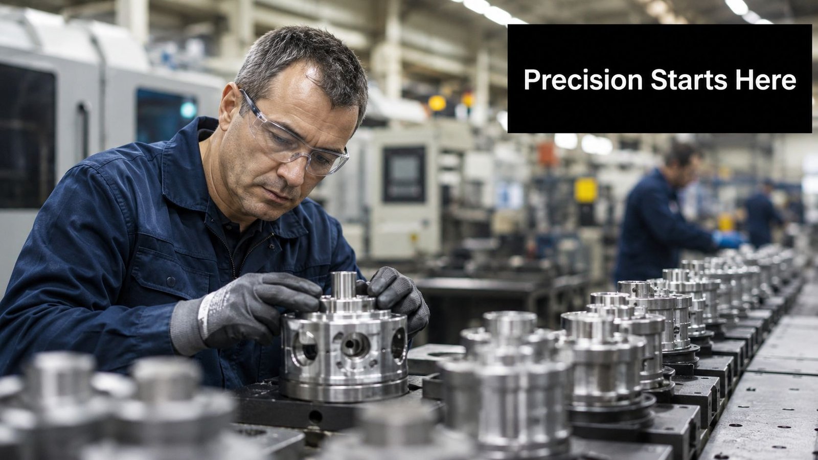
Jigs and fixtures are manufacturing tools used to produce identical and interchangeable components. Fixtures support and locate a workpiece, and that consistent positioning is what enables higher consistency across a production run, supporting repeatability and efficient assembly. Fixture design is one of the most practical ways to reduce variation before it spreads downstream, as explained in the practical construction guidance from Carr Lane's fixture construction reference.
Why the same part keeps acting different
When a part is not referenced the same way every time, small differences become expensive quickly. An operator may compensate with extra force, a weld sequence may pull the part out of square, or an inspection setup may report a result that does not match production reality. A fixture stops that drift by controlling the part directly, removing the need for operators to compensate by feel.
Practical rule: If the process depends on an operator “placing it just right,” the fixture is not finished.
The business case is straightforward. Better fixture design supports repeatability, faster cycle times, safer handling, and less rework. It also makes semi-automated cells more reliable because sensors, robots, and tools all depend on a part arriving in a predictable pose. In that setting, the fixture becomes a direct input to ROI, since it shapes throughput, scrap, and operator effort at the same time.
For teams trying to standardize documentation around parts and setups, manufacturing drawing standards matter because a fixture is only as good as the definition it is built from. Good drawings, clear datums, and sensible tolerances make the fixture easier to build and easier to trust.
What fixture design really does on the floor
Fixture design is the engineering of a workholding system that locates, supports, and clamps a part so its datums stay repeatable during machining, welding, assembly, or inspection. In practice, that means controlling how the workpiece behaves under force, gravity, and operator interaction. It is the difference between holding a part still and holding it correctly.
That difference shows up in margin. If the fixture reduces handling error and speeds loading, the cell becomes easier to run, easier to inspect, and easier to scale. A well-designed fixture also lowers the chance of operator strain and reduces the kind of variation that creates hidden cost in semi-automated work. Experienced manufacturers treat fixtures as production assets, not shop accessories.
Core Concepts The 3 Functions of Fixture Design
A fixture has three jobs, and all three need to work together. If one is weak, the whole setup becomes less predictable. The most reliable designs keep the part in a defined position, resist movement under load, and avoid creating distortion while doing it.
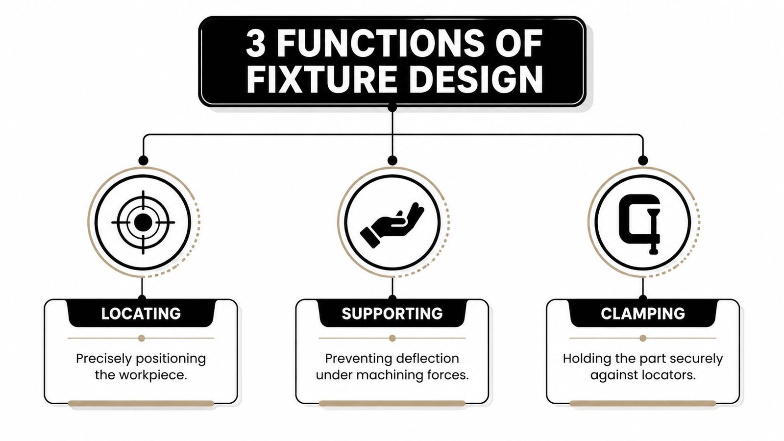
Locating fixes the part's position
Locating answers the question, “Where exactly is the part?” In fixture terms, that means defining the workpiece against known reference points so it sits in the same place every cycle. This is how a fixture controls the part's six degrees of freedom, three linear and three rotational, instead of letting the part float around the setup.
The classic 3-2-1 principle is the cleanest way to think about it. Three points establish a primary plane, two points constrain a second axis, and one point locks the final direction. That logic keeps the part grounded in a repeatable coordinate system, which is why it shows up in so much practical tooling design.
Supporting keeps the part from bending or sagging
Support is often overlooked because the part already appears to be sitting on the fixture. That's not enough. Thin walls, long spans, and flexible components can deflect under gravity or under cutting force, which means the measured or machined shape may not reflect the intended geometry.
For flexible parts, the component should be held in its car-line condition so gravity doesn't change its shape before measurement or assembly. That detail matters in inspection and trim fixturing, where the fixture must represent the part in a realistic, controlled state rather than forcing an artificial one.
Clamping holds it there without overdoing it
Clamping provides the force that keeps the part against the locators and supports. Too little force lets the part shift. Too much force can distort it, especially on thinner components or around heat-sensitive operations.
The best clamp is the one you barely notice in production because it's doing its job without changing the part.
A useful mental model is a tripod plus a hand. The locators define the pose, the supports carry the load, and the clamp keeps everything seated while the operation happens. That's the mechanical heart of fixture design, and it's why a fixture can't be evaluated by clamping force alone.
Key Design Principles for High-Performance Fixtures
High-performance fixtures are judged by what they do on the line, not by how polished they look in CAD. A fixture that holds a part once in the shop but drifts after thermal input, vibration, or repeated loading fails as a production tool. The design has to survive the actual process window, because that is where scrap, rework, and downtime show up.
Precision is about tolerance stack, not just one dimension
A fixture only performs as well as its reference chain. If the base, locators, and clamps do not work together, the part may be held, but not held in a way that supports the required tolerance stack. That is why precision welding fixtures specify locating-surface finishes around Ra 0.8–1.6 μm and verify locating-point accuracy with a CMM to ±0.05 mm. Clamp force and thermal input can still move the part if the fixture is too compliant or poorly referenced, as noted in precision welding fixture guidance.
That level of control pays off most during validation, not after release. Trial loading, trial welding, or inspection against CAD gives the team a chance to correct clamp pressure, shim strategy, or locator positions before production starts consuming time and material. If you need to examine the dimensional chain in a structured way, tolerance stack-up analysis is the right starting point.
Material choice should match the job, not the budget spreadsheet alone
Steel, aluminum, and polymer contact points solve different problems. Steel usually gives stiffness and wear resistance, aluminum helps when weight matters, and non-marring contact elements such as Delrin make sense when the part surface cannot tolerate damage. The wrong material choice often shows up later as wear, part marking, or higher maintenance.
Material selection is also tied to part protection. A fixture that scratches a cosmetic surface or leaves residue on a medical component creates avoidable rework, even if the geometry is correct. In practice, the lowest purchase price is not always the lowest-cost fixture over time, especially when the fixture is expected to run for long periods with limited intervention.
Ergonomics and safety are production variables
Operators have to load, unload, inspect, and sometimes clean the fixture. If the workholding forces awkward reaches, pinch points, or heavy lifts, the cell gets slower and less safe. Good design reduces strain and makes the correct loading motion the easiest one.
A fixture that saves five seconds but increases handling risk is a bad trade, even if it looks efficient on paper.
For medical device work, cleanability and traceability matter too. Surfaces need to be accessible for cleaning, and materials should be chosen so the fixture supports the plant's documentation and control requirements. The fixture may be a mechanical tool, but it still has to fit the quality system around it.
The Fixture Design and Build Process Step by Step
A solid fixture rarely appears from fabrication skill alone. It usually comes from a disciplined sequence where the team defines the problem correctly, models the workholding around the part, and validates the result before it reaches production. That process reduces surprises and keeps the build aligned with the actual line.
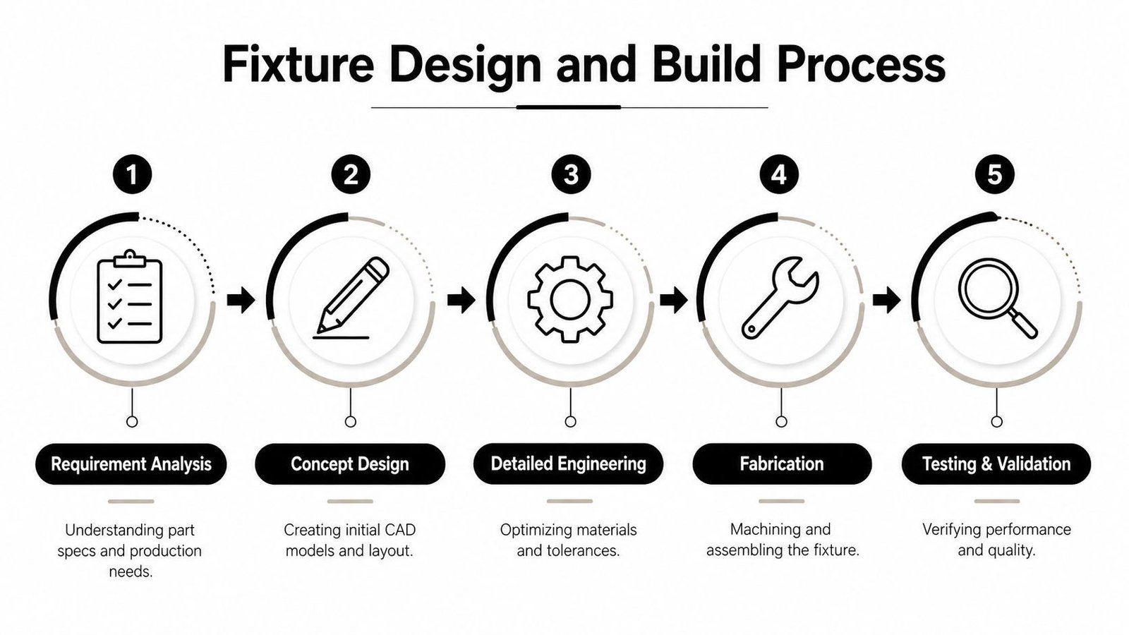
1. Requirement gathering and process review
The first job is understanding the part, the operation, and the failure modes. Engineers need the part geometry, datum scheme, production volume, access constraints, and the operator or robot sequence. Without that, the fixture gets optimized for the drawing instead of the process.
2. CAD layout and manufacturability review
A 3D model shows where locators, supports, and clamps can physically go. It also exposes collisions, access limits, and maintenance issues before metal is cut. Fixture design starts becoming economical here, because avoiding one bad concept is cheaper than reworking steel.
3. Fabrication with the actual process in mind
Fabrication is not just cutting parts to size. It includes selecting stock, machining datum surfaces, finishing locating features, and building the assembly so it can be adjusted if the process reveals variation. The best fixtures are built with the same care as the parts they control.
4. Inspection and verification against CAD
Assembly alone doesn't prove the fixture is right. The team needs inspection, fit checks, and preferably CMM verification against the model so the physical build matches the intended geometry. That step protects the investment before the fixture enters production.
5. Commissioning and operator handoff
A fixture is only finished when it works with the people and equipment around it. Commissioning checks loading, ejection, cycle timing, and safety behavior on the floor. Operator training matters here because the fastest fixture is useless if the team doesn't trust how to use it.
The history of modern fixture design goes back to the Industrial Revolution and Eli Whitney's early work on interchangeable parts, which helped make production more predictable and repeatable, as traced in this historical review of fixture development. That same logic still drives the best builds today, because consistency is what turns a nice tool into a real production asset.
Fixture Applications in Modern Manufacturing
The best way to judge fixture design is to see how it performs on the shop floor. Each process asks for something different, yet the target stays the same. Hold the part so the operation stays repeatable, safe, and fast, while the cell still makes money.
Welding, assembly, and inspection all ask different things
A welding fixture has to resist heat, distortion, and clamp-induced movement. The challenge extends beyond location to holding geometry stable while thermal input tries to change it. That is why welding fixtures are often built with enough rigidity to preserve datum relationships through the weld sequence.
An assembly fixture often carries a different set of priorities. It may need poka-yoke features so the wrong part orientation cannot be loaded, or it may need to present the component at a height that reduces operator strain. In medical device environments, that kind of error-proofing can separate controlled throughput from constant manual correction. In semi-automated lines, better fixture layout also shortens handling time, which improves ROI without changing the core process.
Checking fixtures and semi-automated stations depend on accessibility
Checking fixtures are built for repeatable measurement, so they need stable location and clear access to the features being verified. Their job is to keep inspection consistent across operators and shifts. That is why they are often used with CMMs or vision systems, where the fixture must hold the part still without blocking measurement paths, as reflected in the broader checking-fixture guidance on tooling fixtures and inspection setups.
Semi-automated stations add another layer of pressure on the design. If a robot, screwdriver, sensor, or press head cannot reach the part cleanly, the cell stops behaving like automation and starts needing hands-on recovery. The fixture has to present the part with enough repeatability that the equipment can do its job without rework, delay, or awkward operator intervention. Good access also reduces the chance of pinch points and awkward motions, which matters just as much as cycle time.
Fixed or modular depends on the production pattern
The trade-off between flexibility and efficiency shows up everywhere. Modular fixtures are attractive because they can be reconfigured, but they can also add complexity and reduce stiffness. Fixed, dedicated fixtures are usually the better fit when the process is stable and the volume justifies the higher rigidity and faster cycle.
That trade-off matters most in low- to mid-volume manufacturing, where teams want reuse without giving up accuracy. A reconfigurable system can save changeover effort, but only if the process tolerances and loading pattern support it. Modularity is a tool, not a universal answer, and the right choice depends on whether the fixture needs to support one stable process or several variations without sacrificing throughput.
Maximizing ROI Common Pitfalls and Best Practices
Fixture ROI is won or lost in the details people tend to skip. Over-constraining a part can create distortion, especially when tolerance stack-ups and part variation meet real production loading. Designing for a perfect CAD model instead of the parts that arrive at the station can make a fixture fragile in production. Ignoring maintenance means the cell works well only until wear shows up, then downtime starts eating the return.
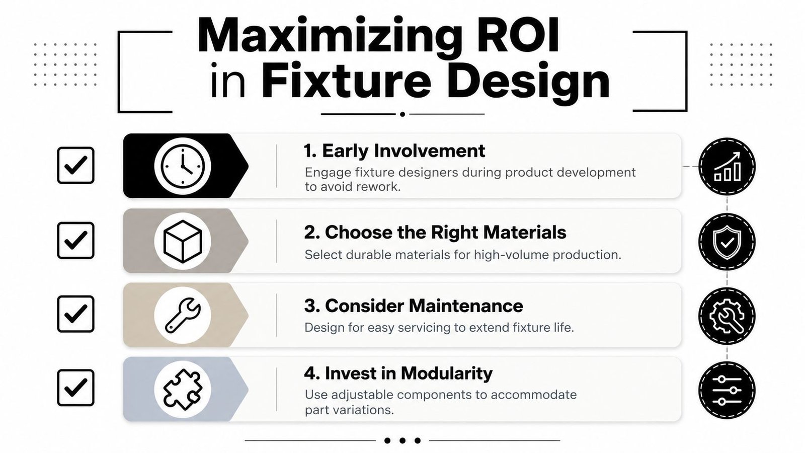
The mistakes that cost the most
- Over-constraining the workpiece: Extra locators or clamp points can induce distortion instead of preventing it.
- Skipping operator input: The people loading the fixture every day usually spot ergonomic or access problems first.
- Designing only for CAD perfection: Real parts vary, and the fixture has to tolerate that variation without forcing bad fits.
- Ignoring serviceability: If worn pads, pins, or clamps are hard to replace, the fixture becomes a maintenance burden.
These mistakes show up in different ways, but they all point to the same issue. The fixture stops supporting production and starts creating avoidable variation, slower recovery, or extra labor.
The habits that pay back
- Involve operators early: They can flag awkward loading motions, pinch points, and access issues before release.
- Build in error-proofing: Poka-yoke features prevent loading mistakes from becoming repeat scrap.
- Plan for maintenance: Service access keeps the fixture in circulation longer and reduces downtime.
- Choose the right integration partner: Deep engineering experience matters because the fixture has to work with the machine, the part, and the people around it.
Those habits matter because fixture design sits at the center of quality, throughput, and safety. A well-designed fixture also makes semi-automated stations more forgiving, since robots, sensors, and tools can only perform well when the part arrives in the right position every time.
The right fixture functions as a control point that improves quality, protects operators, and supports throughput with less dependence on heroic effort from the floor.
System Engineering & Automation designs and builds custom fixtures and semi-automated systems that fit real production constraints, not just clean drawings. If you're looking to improve repeatability, reduce handling risk, and make your line easier to run, visit System Engineering & Automation and see how practical engineering support can turn fixture design into measurable production value.