A production line rarely stops because of one dramatic engineering failure. More often, it stops because a machinist can't tell which surface finish applies, a fixture plate was built to the wrong revision, or a supplier interpreted a projection method differently than the design team intended. The drawing looked “close enough” in the office. On the floor, close enough turns into scrap, delay, and another urgent meeting nobody wanted.
That's why manufacturing drawings standards matter so much to operations teams trying to optimize production and services. They aren't paperwork for auditors or decoration for CAD files. They're the rules that let purchasing buy the right material, fabrication make the right part, quality inspect the right features, and semi-automated equipment run repeatably without constant operator correction.
Table of Contents
- Why Inconsistent Drawings Cost More Than You Think
- The Universal Language of Modern Manufacturing
- Decoding GD&T and Critical Tolerances
- The Anatomy of a Professional Drawing
- ASME vs ISO Key Differences for Global Teams
- Standards in Action a Semi-Automatic Build Workflow
- Your Blueprint for Manufacturing Excellence
Why Inconsistent Drawings Cost More Than You Think
A line can go down over something as ordinary as a missing hole location. Maintenance is waiting. Production is asking for an ETA. Purchasing is calling the supplier. Engineering is opening the model to see what was “obvious” to the original designer but never made it onto the released print.
That kind of failure isn't rare background noise. Missing dimensions constitute 25% of all drawing-related errors in modern manufacturing, with each incident averaging $150,000 in direct costs due to rework and production delays, according to Kevos on engineering drawing checklist failures. For a plant manager, that's the actual meaning of inconsistent manufacturing drawings standards. Not drafting style. Lost output.
Where the cost shows up first
The direct hit usually lands in three places:
- Rework time: Machined parts come back for correction, or can't be corrected at all.
- Schedule disruption: Assembly teams wait while engineering clarifies intent.
- Supplier friction: External shops quote one interpretation and build another.
Those costs multiply when the drawing package controls a semi-automatic station, custom fixture, or validation-sensitive assembly process. If the drawing is vague, the equipment won't “figure it out.” Operators compensate manually, cycle time stretches, and repeatability disappears.
Practical rule: If a feature affects fit, motion, inspection, tooling, or safety, it can't live as tribal knowledge. It has to live on the drawing package.
Why managers feel this as an operations problem
Engineering teams often treat standards as a documentation issue. Operations teams experience them as uptime, yield, labor dependency, and delivery risk. That's a big difference.
When a plant wants better throughput, the first instinct is often to add equipment, add labor, or push suppliers harder. Sometimes that's necessary. But many recurring production losses start earlier, in the release package. A disciplined print release and review process often delivers faster payback than another rushed hardware purchase, especially when teams already suspect they're spending too much on avoidable corrections. A proper production cost analysis for manufacturing operations usually exposes that pattern quickly.
What doesn't work
What doesn't work is relying on smart people to catch unclear intent every time. Good machinists, assemblers, and inspectors can rescue a bad drawing once. They can't build a stable production system around it.
A factory gets more efficient when drawings stop inviting interpretation and start driving repeatable action.
The Universal Language of Modern Manufacturing
A manufacturing drawing isn't just a picture of a part. It's the operating instruction set for everyone who touches the job after design release. Material sourcing, fixture design, machining, assembly, inspection, installation, and service all depend on it.
ISO makes that explicit. ISO 128-1:2020 defines “technical drawing” as the “total package of documentation specifying the product,” including workpieces, subassemblies, and full assemblies, as described by ISO 128-1:2020 technical product documentation scope. That definition matters because it frames the drawing package as the authoritative production reference, not a sketch that gets supplemented informally on the shop floor.
A drawing package is a contract
On real projects, the drawing package answers questions people don't have time to ask twice.
A buyer needs the correct material callout. A machinist needs to know which faces matter. A controls technician needs mounting locations that align with sensors and hard stops. A quality technician needs inspection points that match the design intent. If any of that information sits in an email thread, someone's memory, or a marked-up paper copy at a bench, the system is already fragile.
That's why manufacturing drawings standards are so valuable. They create a shared grammar for dimensions, symbols, notes, line types, views, tolerances, and revision control.
The two main dialects
Most industrial teams work mainly within one of two frameworks:
| Standard family | Common use | What it gives you |
|---|---|---|
| ASME | Often used by North American manufacturers | Structured rules for dimensioning, tolerancing, and engineering drawing practice |
| ISO | Common across international supply chains | Broadly recognized conventions for technical product documentation and global communication |
The important point isn't which family is “better.” The important point is that the whole team reads the same language on the same job.
Why standards matter more in semi-automated production
Manual work can absorb ambiguity for a while. A skilled operator can shim, adjust, sort, or compensate. Semi-automated systems are less forgiving. Fixtures locate where the drawing says they locate. Sensors monitor where components are expected to sit. Tooling repeats exactly what was engineered into it.
A stable automated process starts with stable documentation. If the print leaves room for interpretation, the equipment will repeat the wrong interpretation very efficiently.
That's also why standards help service and support, not just initial build. When maintenance opens a released drawing months later, they need confidence that the file still reflects what's installed. If the package is consistent, spare parts are easier to source, changes are easier to validate, and troubleshooting gets faster.
What strong teams standardize
The strongest operations groups don't leave standards to individual preference. They standardize:
- Templates: Common title blocks, notes, symbols, and release fields
- Review gates: Clear checks before fabrication or supplier release
- Revision discipline: One controlled source of truth
- Supplier expectations: The same conventions across internal and external builds
That discipline lowers confusion before the first chip is cut. It also makes future scaling easier when a plant adds new cells, new vendors, or new product variants.
Decoding GD&T and Critical Tolerances
Basic plus/minus dimensions are useful, but they often leave too much open to interpretation when parts must align, seal, slide, clamp, or assemble in a repeatable way. In precision builds, especially around fixtures and semi-automatic workstations, that ambiguity shows up fast.
A simple way to think about it is directions. Plus/minus tolerances can sound like “meet me near the loading dock.” GD&T, or geometric dimensioning and tolerancing, is closer to “meet me at this exact location, referenced from these known points, with this allowed variation in orientation and position.”
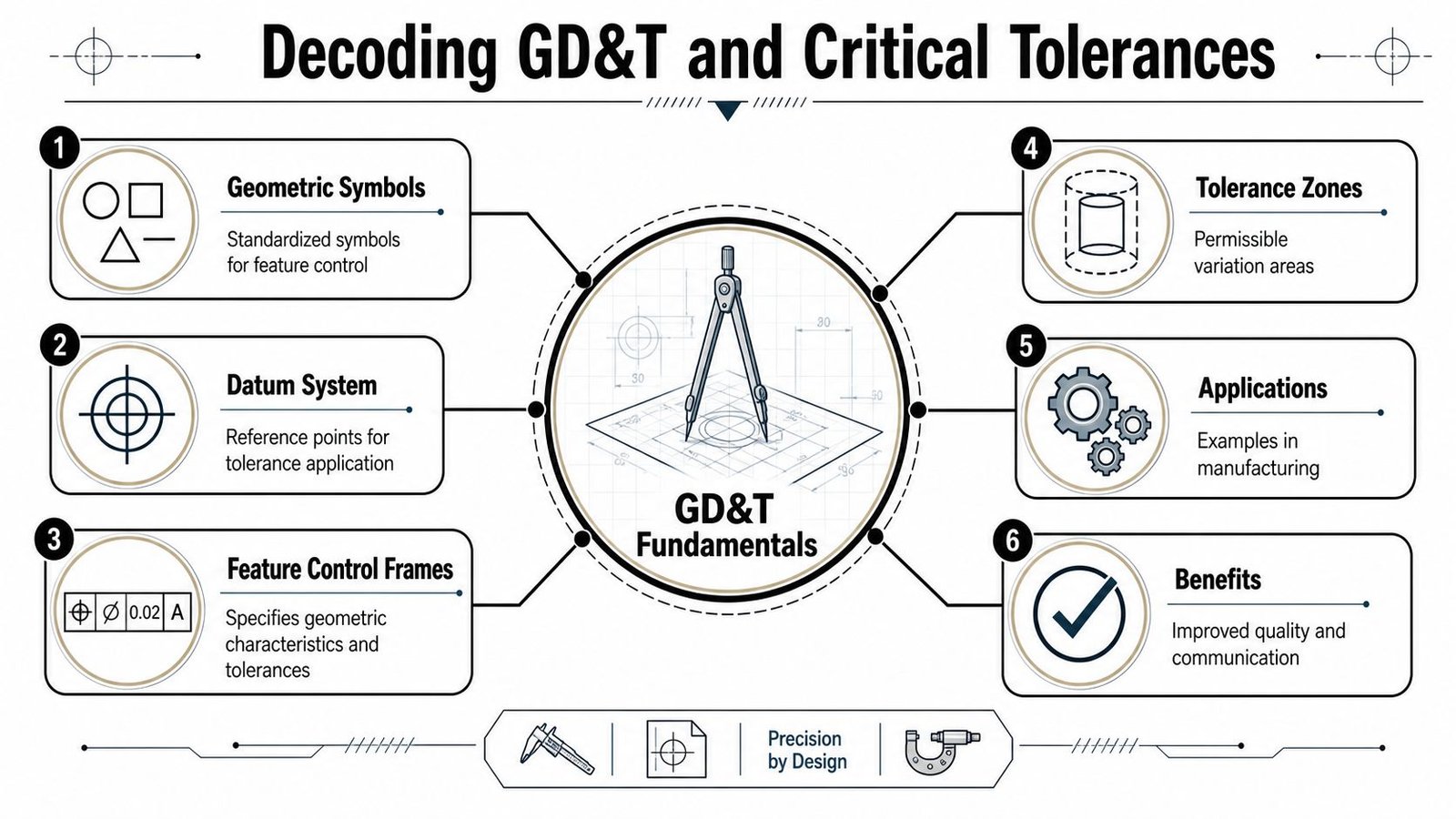
Under ASME Y14.5-2018 (R2024), using form, orientation, and location tolerances instead of simple plus/minus dimensional tolerances reduces functional assembly failure rates by up to 40% in precision automated systems, as summarized by ANSI's overview of ASME Y14.5 and Y14.100. That's the business case in one line. Better tolerance communication leads to fewer parts that technically measure “in tolerance” but still fail in assembly.
Datums are the foundation
A datum is the reference from which the rest of the part is controlled. In practice, datums tell manufacturing and inspection which surfaces or features matter most functionally.
If a fixture plate mounts to a machine base, the mounting face may become the primary datum. A locating edge may become the secondary datum. A dowel hole or slot may become the tertiary datum. Once those references are set, the rest of the geometry can be controlled in a way that reflects how the part functions.
Without datums, teams often inspect features in isolation. That's where false confidence creeps in.
Feature control frames remove guesswork
The feature control frame is the compact box that communicates the geometric requirement. It tells you what characteristic is being controlled, how much variation is allowed, and what datum reference frame applies.
In automated or semi-automated equipment, that detail matters because tooling and sensors don't care whether a feature was “close.” They care whether the part lands in the right place relative to the system.
For tolerance-critical assemblies, a tolerance stack-up analysis for fixture and tooling design is often what separates a smooth launch from a station that needs hand-fitting.
Where GD&T pays off operationally
GD&T earns its keep when function depends on relationship, not just size. Typical examples include:
- Hole patterns for mounting: Position matters more than diameter alone.
- Sliding or mating parts: Orientation and form affect friction and wear.
- Custom nests and fixtures: Location relative to datums drives repeatability.
- Inspection setups: A clear datum reference frame reduces measurement disputes.
Shop-floor insight: If a part has to find its place in a fixture without persuasion, GD&T usually belongs on the print.
The common objection is that GD&T feels harder to read. That's true at first. But vague dimensions cost more than a short learning curve. Once teams understand datums and feature control frames, communication gets cleaner and quality conversations get shorter.
Here's a practical split:
| If you use only plus/minus | If you use GD&T thoughtfully |
|---|---|
| Size may be clear | Function is clearer |
| Inspection can vary by setup | Inspection aligns to datums |
| Assembly issues show up late | Problems get prevented earlier |
| Tooling teams fill in gaps themselves | Tooling teams build to explicit intent |
A short explainer helps if your team is still building confidence with the symbols:
What doesn't work with GD&T
Two mistakes show up repeatedly. First, teams add GD&T symbols without tying them to function. That creates complex-looking prints without improving outcomes. Second, they apply tight controls everywhere, which drives cost without solving a real problem.
The right approach is selective precision. Put geometric control where fit, motion, sealing, alignment, or automation repeatability depend on it. Leave non-critical features appropriately open. Good standards don't mean maximum restriction. They mean clear, economical control.
The Anatomy of a Professional Drawing
A professional drawing tells the truth quickly. You shouldn't need a meeting to learn the revision, material, projection method, general tolerancing basis, finish requirements, or whether the print you're holding is even current.
That's why the title block and its surrounding metadata matter as much as the geometry. They carry the administrative and manufacturing context that keeps a released drawing usable in practice.
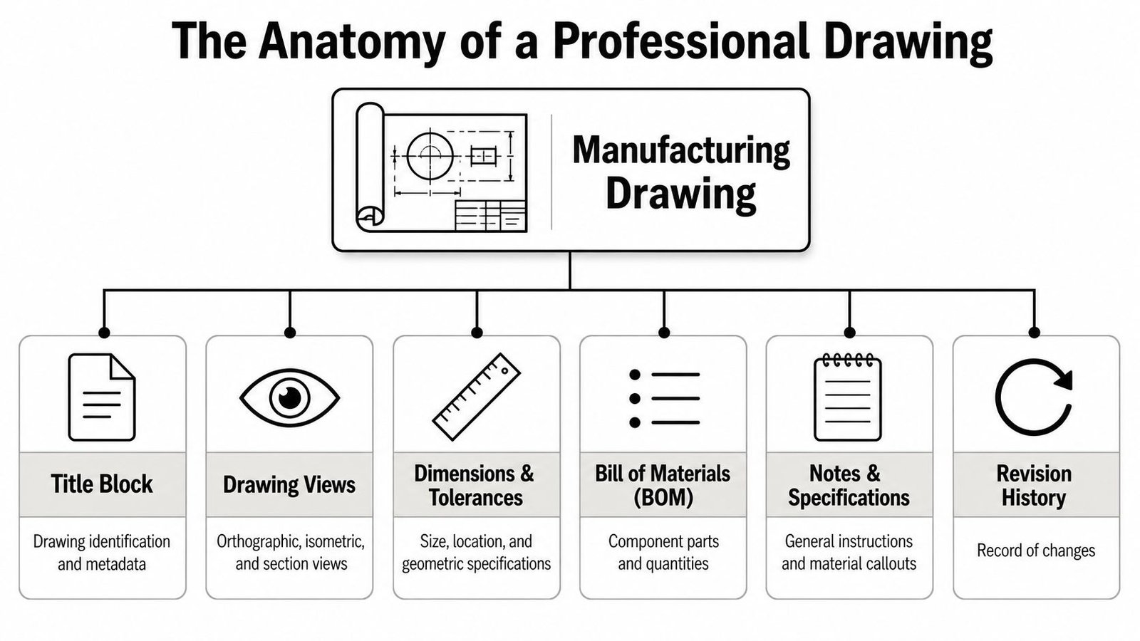
BS 8888 requires the title block to include the projection method symbol, tolerancing standard, surface finish Ra value in µm, and revision status to support traceability in medical device manufacturing, as outlined by this BS 8888 technical communication reference. That's not administrative clutter. Each field affects how the part is made, checked, and approved.
The title block carries production risk
When the title block is incomplete, people compensate with assumptions. That's where avoidable errors start.
A projection symbol tells the reader how views relate. A tolerancing standard tells the supplier which defaults apply when every dimension doesn't carry its own explicit tolerance. A revision field tells everyone whether they're building the latest approved design. A surface finish callout tells machining and inspection what the finished surface must achieve.
If surface finish and tolerancing basis are missing, the intent becomes negotiable. Negotiable intent is expensive.
The fields that deserve scrutiny
The most useful drawing reviews slow down on these items:
- Part number and description: They must match the product structure used in purchasing, inventory, and service.
- Revision level: This prevents old components from re-entering builds after changes.
- Material specification: “Stainless steel” is not the same as a controlled material callout.
- Projection method: Global suppliers can misread view layout if this isn't explicit.
- General tolerancing standard: This fills the gaps where every dimension is not individually specified.
- Surface finish requirement: It drives process choice and inspection expectations.
Notes and specifications do the hidden work
The notes section often carries the process-critical instructions that geometry alone can't express. That may include deburring requirements, coating restrictions, cleaning expectations, or inspection instructions for a regulated environment.
A strong notes list is short but exact. Long notes that read like a legal brief usually signal weak drawing structure. Too few notes can be just as dangerous if key manufacturing constraints never make it into the released package.
The best drawings answer the operator's next question before the operator has to ask it.
How a plant manager should review a drawing
You don't need to redline every callout personally. But you do need a review lens that connects documentation to output.
Ask these questions:
| Review question | Why it matters |
|---|---|
| Is the revision status unmistakable? | Prevents obsolete builds and mixed assemblies |
| Can a supplier identify material and finish without follow-up? | Cuts quoting and fabrication delays |
| Is the projection method visible? | Reduces interpretation errors across regions |
| Are notes specific enough for the process? | Limits floor-level improvisation |
The business outcome is straightforward. Better-structured drawings shorten clarification loops, strengthen traceability, and reduce the number of problems that only appear after fabrication has already started.
ASME vs ISO Key Differences for Global Teams
Most drawing mistakes between regions don't come from advanced theory. They come from teams assuming everyone reads the same conventions. They don't.
ASME and ISO both aim to create clarity, but they don't express that clarity in exactly the same way. If your plant uses domestic suppliers, overseas vendors, contract machine shops, and imported equipment on the same program, those differences become operational, not academic.
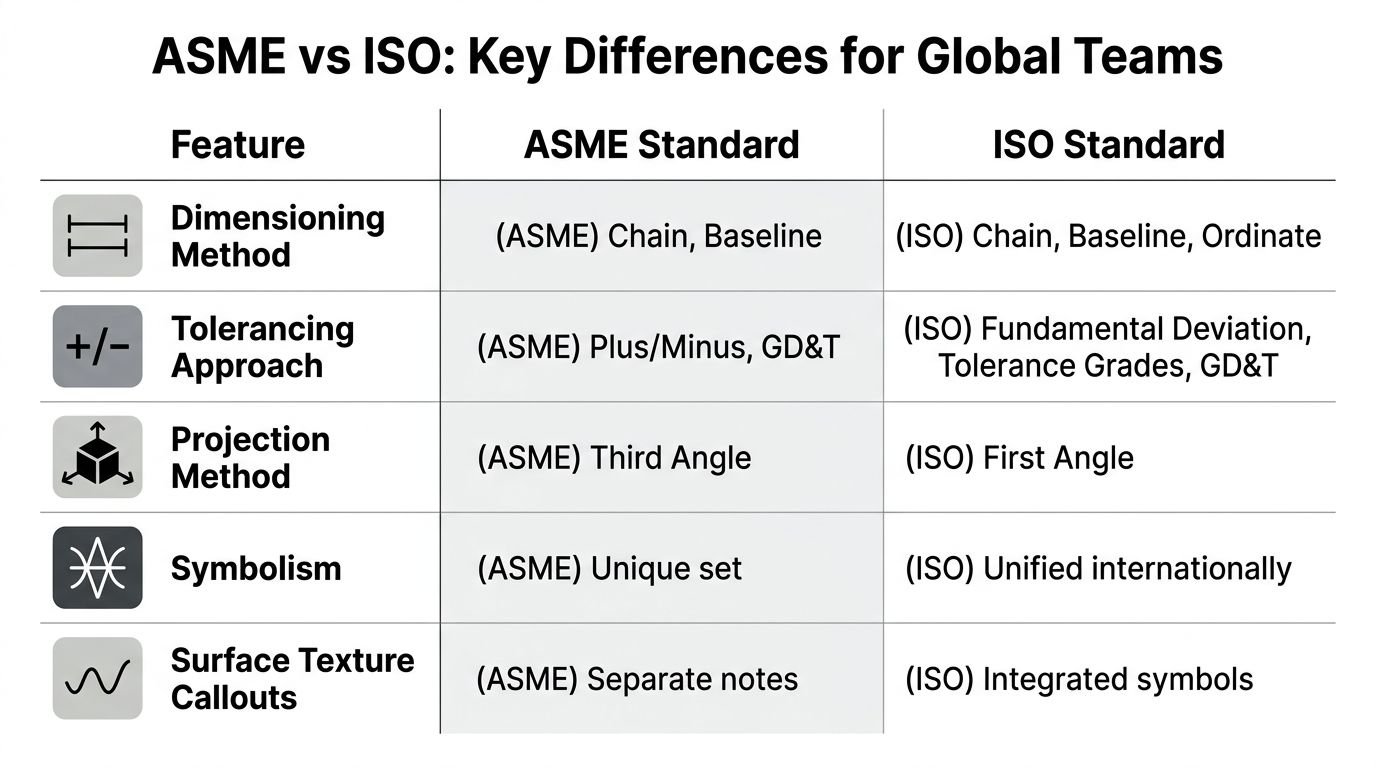
The most common collision points
The first issue is usually projection method. Teams that grew up on one convention often read view placement instinctively, which is exactly why mistakes happen when the opposite convention appears on a print.
The second issue is symbolic and notation style. Diameter, counterbore, surface texture, tolerancing references, and default assumptions can all create friction when suppliers switch between standards families.
The third issue is organizational. Teams often mix standards inside one project because one engineer copied an old template, a vendor reused a house format, or a customer model came in under a different convention.
A practical side-by-side view
| Decision area | ASME environment | ISO environment | Plant-level risk |
|---|---|---|---|
| Projection | Commonly third-angle | Commonly first-angle | Wrong interpretation of views |
| Dimensioning language | ASME-centric notation habits | ISO-centric notation habits | Supplier reads intent differently |
| Tolerance framework | ASME drawing practice | ISO drawing practice | General tolerances applied inconsistently |
| Surface communication | May be handled differently by template and note style | Often tied tightly to ISO conventions | Process selection can drift |
The main danger isn't that one standard is unfamiliar. The danger is hybridization without control.
A recent industry observation is blunt on this point: teams frequently mix ASME and ISO standards across projects, creating interpretation errors, while many resources still don't quantify the operational cost or give managers a framework for enforcing one enterprise-wide standard, as discussed by GetLeo's analysis of engineering drawing standards consistency.
What works for global teams
The cleanest operating model is simple. Choose one primary standard for the enterprise, state it clearly in templates, and control exceptions.
That doesn't mean you'll never receive a drawing from the other system. You will. But incoming exceptions should trigger a translation and review process, not a casual shrug.
Good teams usually define:
- A default enterprise standard: One drawing language for internal release
- Supplier onboarding rules: Vendors know what conventions they're expected to follow
- Conversion checks: Imported drawings get reviewed before release to production
- Template governance: Engineers don't improvise their own title blocks and note structures
Mixed standards are manageable when they're deliberate. They're costly when they happen by accident.
What doesn't work internationally
What doesn't work is relying on experienced people to “just know” which standard a drawing is using from visual feel alone. That breaks down with new hires, new suppliers, shift changes, and compressed schedules.
Plants that optimize production don't leave interpretation to experience level. They make the standard visible, repeatable, and enforceable.
Standards in Action a Semi-Automatic Build Workflow
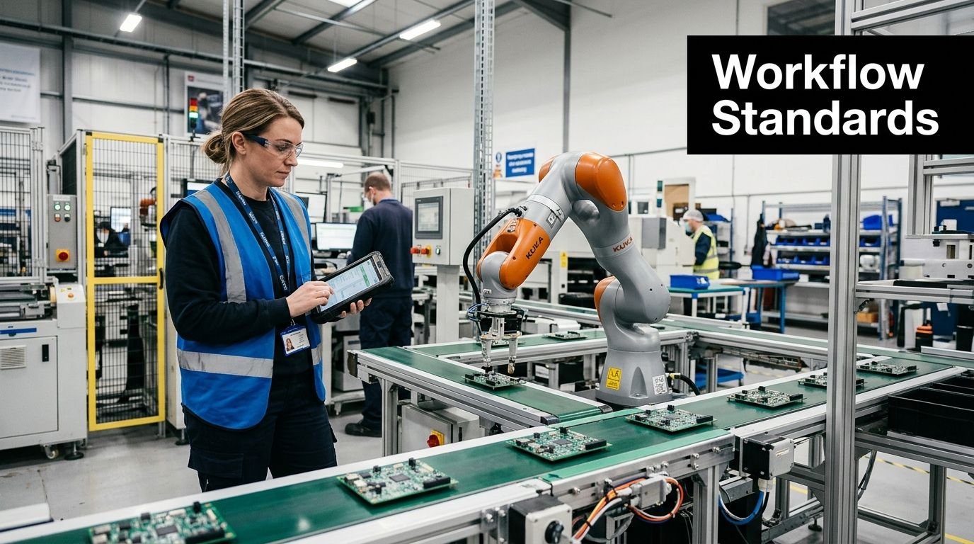
The value of standards becomes obvious during a semi-automatic equipment build. Not during the kickoff meeting. Not in the polished CAD review. During fabrication, assembly, debug, and commissioning, when every unclear assumption turns into real delay.
A typical workflow starts with a product handling problem. Parts need repeatable orientation, better operator ergonomics, lower manual variability, and cleaner inspection. The solution may be a semi-automatic workstation with custom tooling, guided motion, sensors, and controlled assembly steps.
How the drawing package drives the build
At concept stage, the 3D model carries layout, interference checks, reach, and overall architecture. As the project moves into release, the drawing package takes over where production needs exact instructions.
The fixture base needs mounting geometry tied to functional datums. The nest needs controlled contact surfaces. Pneumatic bracketry needs mounting locations that match purchased hardware. Guards, sensor tabs, and adjustment features need dimensions that assemblers and inspectors can verify without opening the CAD model and guessing what matters.
That's where a standards-based package earns its keep. It gives fabrication, assembly, and quality the same operating reference.
The shift toward model-based definition
Current best practice is moving toward model-based definition, where 3D models drive production and 2D drawings focus on measurable features such as caliper or micrometer points, as noted in this discussion of model-based definition and compliance validation. That shift is useful, but it creates a practical responsibility. Teams still need a disciplined method for deciding what remains on the 2D print and how compliance gets checked when the model is primary.
In semi-automatic builds, that usually means the model carries full geometry while the 2D drawing highlights what the floor must build, inspect, and maintain without ambiguity.
A workflow that holds up under pressure
The strongest projects tend to follow a pattern:
Functional references get defined early
Designers decide which faces, holes, and interfaces drive location and repeatability.Release documents match shop reality
The drawing includes revision control, purchased-part references, finish requirements, and measurable inspection features.Fabrication receives controlled information
Suppliers don't reverse-engineer intent from screenshots or informal markups.Assembly builds to one source of truth
The mechanical team, controls team, and quality team all work from the same released data set.Commissioning confirms performance against documented intent
Adjustments are made inside a controlled process, not through undocumented floor fixes.
For companies evaluating semi-automatic performance assembly solutions, project risk declines. Better documentation shortens debug, reduces hand-fitting, and makes future maintenance less dependent on the memory of the original build team.
Where standards save time later
The long-term payoff often shows up after install. Spare parts can be ordered correctly. Replacement tooling can be fabricated without chasing an old engineer for clarification. Validation and change control are easier to support because the released package documents intent cleanly.
That's the practical link between manufacturing drawings standards and operational efficiency. Better standards don't just help you build the first machine. They help you keep the process stable after the machine enters production.
Your Blueprint for Manufacturing Excellence
Manufacturing drawings standards are easy to underestimate because they sit upstream of the visible action. Operators run the line. Technicians maintain the station. Supervisors chase output. But those daily results depend on how clearly the product and process were documented before production began.
The strongest plants treat drawings as production assets. They know a complete title block protects traceability, GD&T protects functional assembly, and a controlled standard protects supplier communication. They also know that semi-automation only performs as well as the documentation behind its fixtures, nests, stations, and inspection points.
The ISO 128 family, which debuted in 1982, now serves as a “common language” for designers, manufacturers, suppliers, and customers, helping optimize production services and reduce labor dependency caused by ambiguous communication, according to the ISO 128 overview. That phrase, common language, captures the point well. Standardized drawings let different teams act on the same intent without repeated interpretation.
The practical takeaway
If you want higher throughput, fewer build errors, smoother supplier handoffs, and more reliable automation, start with the drawing package. Review how your team handles standards selection, GD&T application, title blocks, revisions, and release control. Then tighten the weak points that force the floor to improvise.
A plant doesn't become more efficient because its drawings look cleaner. It becomes more efficient because clear drawings reduce misreads, shorten decision loops, and let equipment and people work from one trusted source.
Good manufacturing documentation doesn't slow production down. It removes the confusion that slows production down.
That's the business value of mastering manufacturing drawings standards. Better quality. Better repeatability. Better use of labor. Better odds that the next equipment upgrade delivers the ROI it promised.
If you're evaluating ways to improve throughput, reduce labor dependency, or build more reliable semi-automatic equipment, System Engineering & Automation can help. SEA designs and delivers practical automation, custom tooling, fixtures, and GMP-aware manufacturing solutions that align engineering documentation with real production needs, from concept through installation and ongoing support.