

Your line is running, but the operator keeps stopping to reposition a part before the next operation. Quality is sorting a batch with inconsistent hole locations, and the next changeover needs another round of adjustments. Before you price a robot or add another inspection step, check how the part is being held.
Fixtures in manufacturing address that basic problem. The right fixture gives operators a reliable way to position and secure a workpiece, whether they're drilling a bracket, assembling a medical device or checking a finished weldment. Choosing one starts with the process, not the level of automation.
Table of Contents
- What a Fixture Does on the Production Floor
- Fixture Types and Where Each One Fits
- How Fixtures Make Every Part Repeatable
- Choosing a Fixture by Volume, Mix and Cost
- What Regulated Production Asks of a Fixture
- Fixing Common Fixture Problems
- Confirm Your Fixture Plan Before You Build or Buy
What a Fixture Does on the Production Floor
Two operators drill the same bracket. One checks each blank by eye against a mark, adjusts it and tightens a vise. The other drops the bracket into a fixed pocket, seats it against a stop and closes a clamp.
The pocket works like a cookie cutter: it establishes the same outline without asking someone to measure it again. The operator still needs the correct drill, cutting conditions and work instructions, but positioning no longer depends on judgment.
A fixture holds a part in a repeatable position during production or inspection. People sometimes use the term for devices that also guide a tool, although a tool-guiding device is more precisely called a jig. A drill bushing guides the drill; a fixture locates and holds the bracket.
The three jobs of a fixture
- Locate: Datum faces, pins and nests establish where the part sits.
- Support: Rest pads and backing surfaces prevent deflection under cutting, pressing or assembly forces.
- Clamp: Clamps keep the part against its locators without distorting it.
The 3-2-1 locating principle illustrates the arrangement. Three contact points establish the base plane, two establish a side plane and one establishes an end position. With suitable clamping to maintain contact, the arrangement constrains the part's six degrees of freedom without relying on excessive locating contacts.
The contrast between manual positioning and a fixed locating route is shown below.
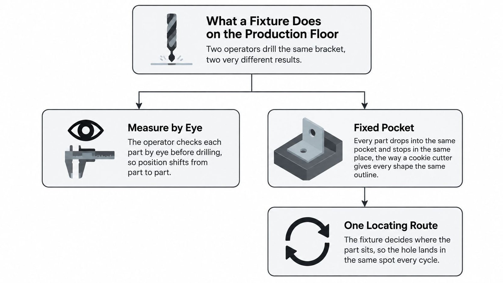
These functions apply at drilling, welding, assembly and inspection stations. The required forces change, but the engineering questions remain recognizable: where does the part touch, what resists the process load and what keeps it seated?
Manufacturers are considering improvements at several levels: 46% ranked process automation among their first or second investment priorities for the next two years, according to Deloitte's manufacturing trends report. That doesn't mean every workstation needs full automation.
A fixture doesn't make an inaccurate process accurate. It makes the part arrive in the same place, so engineers can separate positioning variation from the variation that remains in the process.
Fixture Types and Where Each One Fits
Use this comparison to narrow the options before discussing mechanisms or controls. Relative setup costs are qualitative, not quotations: fixture size, machining access, accuracy, controls and installation scope affect the final cost.
Fixture types, how they hold parts and relative cost
| Fixture type | How it holds the part | Best fit | Relative setup cost |
|---|---|---|---|
| Manual clamp fixture | Bolt, strap or toggle clamps tightened by hand | Low-volume work and manual cells on tight budgets | Low |
| Assembly or nest fixture | Locators and pins position sub-components for joining | Manual or semi-automatic assembly | Low to medium |
| Inspection (gauge) fixture | Holds the part in a reference position for measurement | First-article and in-process quality checks | Low to medium |
| Pneumatic fixture | Air cylinders close clamps on a fixed cycle | Repeat parts with cycle-time targets | Medium |
| Vacuum fixture | Suction holds thin, flat or non-metallic parts | Sheet, panels and parts that clamps would deform | Medium |
| Welding fixture | Rigid frame holds parts against heat distortion | Repeat weldments | Medium |
| Modular zero-point fixture | Interchangeable pallets on a fixed reference system | High-mix work with frequent changeover | Medium to high |
| Hydraulic fixture | Oil pressure provides high clamping force | Heavy castings and high-force machining | High |
| Sensorized fixture | Sensors confirm part presence, clamp force or position | Processes where one missed defect is costly | High |
Manual and powered choices
Manual fixtures are the starting point for low-volume work with limited budgets. A toggle-clamp fixture can secure a fabricated bracket, while an assembly nest can hold a housing and cover in alignment during fastening. Keep handles accessible and make the seated position easy to inspect.
Powered fixtures reduce repeated clamping effort and make the clamping sequence more consistent. Pneumatic cylinders suit repetitive loading cycles; hydraulic mechanisms suit applications requiring high force in a compact arrangement. Neither should substitute for adequate support beneath the workpiece.
Vacuum workholding solves a different problem. For a thin panel that would bow beneath concentrated clamps, a supported vacuum surface distributes holding force. Check sealing, leakage, available holding area and resistance to sideways cutting loads before choosing it.
Specialist fixtures
A welding fixture must provide torch access and allow removal after cooling, not just hold the unwelded pieces together. An inspection fixture must expose the features being measured while establishing the intended reference position.
Modular zero-point systems prioritize repeatable changeover. Sensorized fixtures add confirmation, but a sensor isn't a replacement for sound mechanical location.
For example, a fabricated enclosure might need a welding frame during joining and a separate gauge fixture for first-article approval. The same product can need different fixtures because each operation applies different loads and checks different features.
When defining custom workholding fixtures, shortlist alternatives by the failure you need to prevent. For a delicate housing, compare a supported nest with controlled clamping against vacuum workholding, rather than automatically selecting the strongest clamp.
How Fixtures Make Every Part Repeatable
The main sources of positioning variation are operator placement, part-to-part tolerance and changing clamp force. A fixture controls placement by giving the operator a defined loading route, but it doesn't erase variation already present in incoming parts.
The illustration separates these sources so troubleshooting doesn't stop at operator technique.
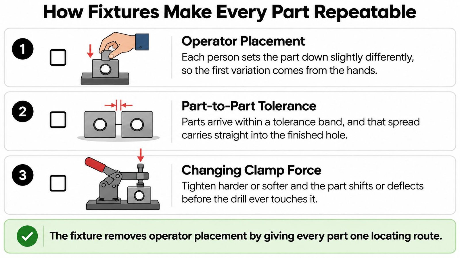
Locate from the datum surfaces identified on the drawing, not whichever edge is easiest to reach. If a hole's position is specified from a machined face, locating from an inconsistent cast edge can produce a fixture that repeats the wrong relationship perfectly.
Build error-proofing into the loading geometry. An asymmetric locator arrangement can prevent reversed loading; part-presence sensing can confirm that a component is there. Presence alone doesn't prove full seating, so position the sensing point to detect the condition that matters.
Run a practical repeatability check
For an initial shop-floor trial, use the following sequence. It's a diagnostic starting point, not a substitute for a risk-based validation protocol.
- Load and measure ten or more representative parts. Include repeated unloading and reloading, and involve different trained operators where relevant.
- Record the dimensional spread against the drawing tolerance. Confirm that the measurement method can distinguish fixture variation from measurement variation.
- Document clamp settings and operating sequence. Include the loading direction, seating checks and the order in which clamps close.
- Establish wear checks and remeasurement triggers. Identify critical locator dimensions and specify checks after repair, impact or configuration changes.
When positioning variation is causing rejects, controlling it can reduce scrap and rework. For a welded frame, rigid supports and a defined weld sequence can keep distortion within a more consistent band, but measure after release and cooling. Measuring only while the assembly is clamped can hide springback.
The video below provides an additional visual reference for fixture concepts.
Flexibility adds verification work. Interchangeable nests and adjustable locators need identifiable configurations, controlled settings and acceptance checks after changes.
Research on reinforced PA6 GF30 additively manufactured clamping components reports feasibility while identifying anisotropy, process parameters and mechanical performance as areas requiring further assessment. Don't approve a printed fixture solely because it fits the part. Assess stiffness, contact wear and performance under the actual operating conditions.
Choosing a Fixture by Volume, Mix and Cost
Suppose a sensorized fixture could prevent one escaped defect each month. In that hypothetical case, multiply the full cost of an escaped defect by twelve, then compare the annual avoided cost with the annualized cost of sensors, integration, validation and upkeep.
Include investigation, containment and customer handling in the defect cost where applicable. If the incremental return is negative and no safety or quality requirement mandates sensing, a modular manual or semi-automatic option may be the better purchase.
Compare the whole operating cost
A useful decision starts with annual volume per part number, variant count, measured changeover time, labor availability and the consequence of an escaped defect. Then account for:
- Purchase and integration: Fixture construction, guarding, PLC interfaces and connections to quality systems.
- Validation and maintenance: Acceptance testing, documentation, replacement components and calibration where applicable.
- Operating savings: Reduced handling, faster changeovers and avoided scrap or rework.
- Downtime exposure: Troubleshooting, spare-parts availability and recovery after a sensor or actuator fails.
Workholding market coverage identifies sensor-enabled workholding, modular fixtures, zero-point clamping and automation compatibility as emerging trends. Those developments don't establish a universal production volume at which sensors become worthwhile. Smart doesn't automatically mean higher return.
Recommended fixture level by production profile
| Production profile | Recommended fixture level | Main reason |
|---|---|---|
| High volume, one part number | Dedicated pneumatic or hydraulic fixture | Fixed geometry and cycle time justify the engineering effort |
| Medium volume, few variants | Pneumatic fixture with interchangeable nests | Quick nest swaps keep one fixture base |
| High mix, low volume | Modular manual or semi-automatic fixture | Preserves flexibility and avoids changeover complexity |
| Labor-constrained, repetitive task | Semi-automatic fixture with guided steps | Holds consistency when staffing is tight |
| Critical quality or traceability need | Sensorized fixture with logged signals | Data shows each cycle ran inside limits |
Treat each row as a starting point, not an automatic specification. Logged signals demonstrate only the conditions measured, so select pressure, vacuum, part-presence, locator-position or torque signals according to the failure mechanism.
Labor constraints also matter. A Deloitte and Manufacturing Institute analysis estimated that 1.9 million U.S. manufacturing jobs could remain unfilled over the following decade if workforce challenges aren't addressed, as discussed in Deloitte's manufacturing labor analysis.
Buying rule: Automate the repetitive action that constrains production, not every action the operator performs.
For frequent product changes, evaluate quick-change fixtures alongside cycle-time improvements. A fixture that saves handling during production can still be a poor investment if setup consumes the gain. Leave room to increase assistance as volume grows.
What Regulated Production Asks of a Fixture
In medical-device production, a fixture can affect more than part position. It may touch a finished surface, collect residue or make inspection harder, so its design belongs in the documented quality system alongside the production process.
Process controls must address deviations that could cause products to miss specifications. In practice, this means clear work instructions, validated settings where required, and traceable adjustments. A fixture's approved setup should be clear to the people operating and maintaining it.
Treat contact points as quality decisions
A medical-device company used locator pins on a rotating dial to position products in a semi-automated system. The pins scratched the product surface. A custom insert that positioned each product by its edge replaced the pins and eliminated that source of scratching.
Every contact point can affect quality. A fixture may locate a part accurately and still damage its cosmetic surface, create debris or obstruct inspection. Check surface condition as well as dimensional location.

Design for adjustment, cleaning and maintenance. For example, a deep pocket may locate a product securely but trap residue or block access for inspection. Review drainage, access beneath inserts, fastener recesses and whether maintenance could disturb a critical setting. A fixture that produces parts within dimensional limits may still create problems if it is difficult to clean or inspect. For practical background, see these GMP practices.
Keep the fixture's configuration traceable
Set user needs and acceptance criteria before design approval. Specify which settings operators can adjust, which changes need authorization and what verification follows. These controls connect the fixture to the manufacturer's quality system rather than leaving it as an isolated engineering asset.
Keep controlled records that answer what the fixture is approved to do and how its condition is maintained:
- Identity and configuration: Fixture identifier, approved drawings, revision and compatible product variants.
- Intended use: Product requirements, critical contact points and process risks.
- Acceptance evidence: Inspection results, repeatability testing and validation records where applicable.
- Operating controls: Approved instructions, settings, loading sequence and adjustment permissions.
- Materials and cleaning: Contact materials, cleaning method and inspection access.
- Lifecycle history: Maintenance, locator replacement, calibration where relevant, deviations and change approvals.
Production and quality personnel should be able to confirm that the fixture at the station matches the approved configuration. That check ties the physical tool to its documented requirements, operating controls and maintenance history.
Fixing Common Fixture Problems
Parts shifting between cycles should prompt a check for worn locators or debris on locating surfaces before anyone changes the machine program. A chip beneath a datum can resemble a machining problem, while a loose stop can resemble inconsistent loading.
Follow a deliberate diagnostic order: inspect datums and locators, check clamp force and supply pressure, examine incoming part variation, then observe operator loading. That order helps avoid blaming the operator for a mechanical condition.
Match the symptom to the mechanism
Fixture symptoms, likely causes and fixes
| Symptom | Likely cause | Fix |
|---|---|---|
| Parts shift between cycles | Worn locators or debris on locating surfaces | Clean datums, replace worn pins and check locators on a set schedule |
| Dimensional drift over a shift | Clamp force loss or falling air or hydraulic pressure | Check supply pressure, verify clamp force and log readings |
| Scratches on a finished surface | Metal locators contacting a cosmetic face | Relocate contact to an edge or non-critical datum, or use an insert |
| Parts will not seat fully | Chips, burrs or incoming part variation | Add chip clearance and check incoming part tolerance |
| Operator loads the part wrong | No error-proofing or unclear orientation | Add asymmetric locators or presence sensing |
| Long changeover | A dedicated fixture for each variant | Move to modular nests or zero-point plates |
Use a go/no-go gauge suited to the locator feature for a quick wear check. Compare pneumatic or hydraulic pressure readings with the approved setpoint while the fixture operates, not only when it's idle. Pressure indicates supply conditions; linkage friction or binding can still reduce actual clamp force.
Gradual dimensional drift warrants checking pressure loss before assuming locator wear. If pressure remains stable, investigate thermal effects, fastener movement and workpiece variation.
Don't adjust the process to compensate for an unverified fixture fault.
Cleaning, a pressure correction or replacement with an approved locator can be checked during a shift, followed by documented release checks. Changes to datum strategy, contact geometry or modular architecture need engineering review and repeatability testing before production release. A faster changeover isn't an improvement if the replacement nest establishes a different reference.
Confirm Your Fixture Plan Before You Build or Buy
A useful purchase specification starts with the part and the production constraint. Keep the first version short enough for production, quality and engineering to review together, but specific enough to prevent assumptions about loading, acceptance and changeover.
Build a one-page engineering brief
List the production profile. Record each part's annual volume, variants and current changeover time. Include the drawing revision and expected product changes so the engineer can distinguish stable requirements from temporary needs.
Map where variation begins. Observe locating, clamping and operator loading separately, then identify the operation where the defect first appears. Attach a marked-up photograph or sketch showing contact points, tool access and the feature that fails.
Select a provisional fixture level. Match the production profile to a manual, powered, modular or sensorized approach. For a smart option, test the incremental payback and state exactly which failure the signal must detect.
Record quality requirements before design starts. Include acceptance criteria, cleaning access, adjustment permissions and change-control expectations. Identify who will approve the fixture and what evidence they'll need for release.
Book a no-obligation consultation. In our manufacturing automation consultation, we work to understand current bottlenecks, labor and production constraints, quality or consistency concerns, and budget and timeline expectations. Our team evaluates production workflows to identify where automation can have the greatest impact.
For a largely manual line, the sensible first investment may be tooling and fixtures rather than automation. Semi-automatic operation can follow when the task and production demand justify it, with full automation considered when it makes operational and financial sense.
The concrete output is a one-page consultation brief containing the part family, production profile, current failure, proposed fixture level, acceptance requirements and project constraints. Bring representative parts and the relevant drawings so the discussion can focus on the actual interfaces, not an assumed version of the process.
System Engineering & Automation offers custom tooling and fixtures, manual equipment and semi-automatic systems, supported by design, installation, commissioning and ongoing service. Visit System Engineering & Automation to arrange a no-obligation consultation and review where better workholding or targeted automation could address your production bottleneck.