
You're reviewing a housing drawing before approving a new workstation. The machinist is confident about the dimensions, quality has a measuring routine ready, and the fixture concept looks straightforward. Then someone asks which surfaces locate the housing in the finished assembly, and the answers don't match.
That's the point where knowing how to read manufacturing drawings becomes more than recognizing symbols. Before committing to tooling, sensors, or automation, the team needs a shared interpretation of what the part must do, how it must be held, and how conformity will be demonstrated.
Table of Contents
- Why Drawing Literacy Is a Production Decision
- Reading the Title Block and General Notes First
- Understanding Views, Sections, and the Bill of Materials
- Decoding Dimensions, Tolerances, and GD&T Symbols
- Translating Drawings into Fixtures, and Inspection Plans
- When the Drawing Is Not the Only Source of Truth
- A Practical Checklist and When to Bring in Mechanical Expertise
Why Drawing Literacy Is a Production Decision
Consider a hypothetical fixture built to locate a housing against its convenient outside walls. The operator loads it easily, the clamps hold securely, and the drilled holes meet their diameter limits. At assembly, however, the hole pattern doesn't align with the mating component because the drawing locates it from a different functional reference.
The team technically read the drawing, but they didn't translate its requirements into the fixture. Correcting that mistake could require new locators, revised machining programs, another inspection setup, and disposition of parts that can't be recovered. The expensive misunderstanding wasn't the hole size. It was how the housing was supposed to be located.
Read for the production consequences
ASME Y14.5 establishes a common language for form, fit, function, and interchangeability, including requirements that affect datum interpretation, tooling, and measurement. Its requirements belong in production planning, not just drafting discussions, as explained in ASME's dimensioning and tolerancing overview.
An operations manager should therefore ask different questions from someone checking whether dimensions are present:
- Workholding: Which features must the fixture locate, and which surfaces can safely accept clamping force?
- Process selection: Can the planned equipment produce the required relationships without relying on repeated operator adjustment?
- Acceptance: Will quality evaluate the part in the same reference system used to define its function?
- Investment: Does the requirement justify a dedicated gauge, additional sensing, or a more controlled workstation?
Practical rule: Don't approve a fixture concept until engineering, manufacturing, and quality agree on how the part is located and accepted.
For SEA, translating drawings into manual and semi-automated workstations means resolving those questions before designing equipment around them. A sensor attached to the wrong reference won't correct a misunderstood requirement.
The useful output of drawing review isn't a marked-up print alone. It's a production decision package: a defensible setup, an operation sequence, an inspection strategy, and a list of unresolved questions. That's what allows manufacturers to optimize production without buying complexity they don't need.
Reading the Title Block and General Notes First
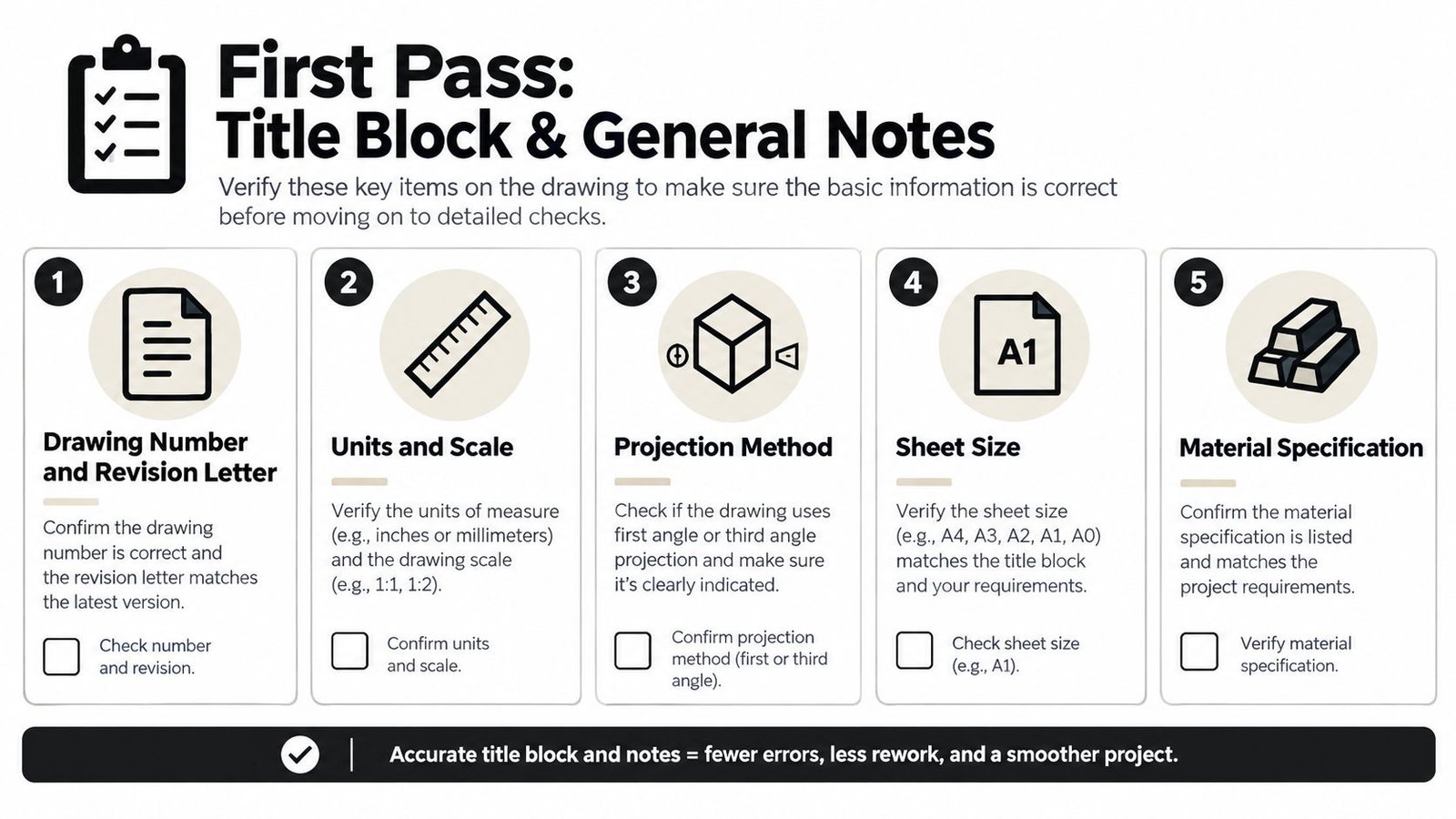
Start with document identity, not the most prominent dimension. Confirm the drawing number and part identity, then the released revision and its relationship to the work order. A familiar-looking print isn't evidence that it governs the current build.
Check the remaining fields in a deliberate order:
- Units: Establish the unit system before transferring values into machining or inspection software.
- Projection method: Confirm first-angle or third-angle projection before interpreting view placement.
- Scale: Use stated dimensions rather than measuring the displayed or printed geometry.
- General tolerances: Identify which default requirements apply where individual limits haven't been specified.
- Sheet configuration: Check sheet size, completeness, and references to additional sheets.
- Material and processing: Reconcile the material specification, finish, heat treatment, coating, and applicable process restrictions.
This checklist supports that first-pass review.
Confirm the governing standard
The drawing revision and the referenced standard revision are separate checks. ASME Y14.5-2018 replaced the 2009 edition, so engineering, inspection, tooling, and automation teams should confirm which edition the drawing invokes before programming equipment or approving inspection methods, as documented in ASME's Y14 standards information.
Don't automatically apply the newest edition to a legacy drawing. Follow the controlled specification, and ask engineering to resolve an absent or unclear reference. A different governing edition can change interpretation even when the visible callout looks familiar.
Treat notes as manufacturing requirements
General notes can change how a part must be processed, protected, or inspected. Review surface-texture callouts, weld symbols, finish requirements, and process notes together rather than sending each to a different department without coordination.
A coating requirement, for example, should trigger a planning question about when the applicable feature is measured. A process restriction should be checked before choosing the operation sequence. If the drawing doesn't clearly establish the intended condition, request clarification rather than making a convenient assumption.
Don't apply title-block tolerances to dimensions that already have individual limits. Keep default requirements and feature-specific requirements distinct in the inspection plan.
Treating the title block as administrative is a poor shortcut. The fixture designer, machinist, purchasing team, and inspector all need the same configuration before their individual decisions can agree.
Understanding Views, Sections, and the Bill of Materials
A feature that looks like a simple opening in the front view might be a stepped bore, an intersecting passage, or a recess with restricted tool access. Reconstruct the geometry before judging the manufacturing method. Start with the overall shape, then trace important features across the related views.
Use orthographic views to establish feature relationships and an isometric view, when provided, to support spatial understanding. Don't let the more intuitive isometric image replace the dimensioned definition. Follow the confirmed projection method rather than assuming view placement from habit.
Follow a feature through the drawing
For a bearing seat or mounting interface, trace the outside outline, centerline, internal geometry, and relevant section reference. A section view reveals geometry at the indicated cutting plane; a detail view enlarges a local area without redefining the whole part.
Hidden lines deserve deliberate attention. They can indicate an internal boundary that affects cutter access, a remaining wall, or an intersection that isn't apparent from the visible outline. Read section hatching, cutting-plane direction, and view labels together so you don't confuse an internal feature with an exposed surface.
A feature isn't understood until its views, dimensions, and associated notes tell a consistent story.
The recommended two-pass approach includes reconciling view and section references, hidden lines, detail views, and process notes before verifying individual characteristics. That workflow is included in the drawing-interpretation study's manufacturing review discussion.
Read the assembly configuration, not just the shape
The bill of materials, where applicable, connects assembly callouts to the components the team must manufacture or procure. Use it alongside the assembly drawing and individual part definitions:
- Part identity: Match item references to part numbers and controlled component documents.
- Material condition: Reconcile material callouts with heat treatment, coatings, and finishing notes.
- Purchased hardware: Confirm the specified fasteners and mating components rather than substituting by appearance.
- Make-or-buy status: Establish which items require internal manufacturing planning and which need purchasing verification.
For an assembly workstation, those distinctions affect loading access, component presentation, and the operation sequence. A fixture concept shouldn't depend on access that disappears once another component is installed.
Surface-finish symbols also belong in this configuration review. Identify the affected surface and connect it to the relevant operation and acceptance requirement. Don't assume that a visually similar machined surface meets the specified condition.
Before moving on, the team should be able to describe the part's geometry and assembly configuration without relying on guesses about anything hidden.
Decoding Dimensions, Tolerances, and GD&T Symbols
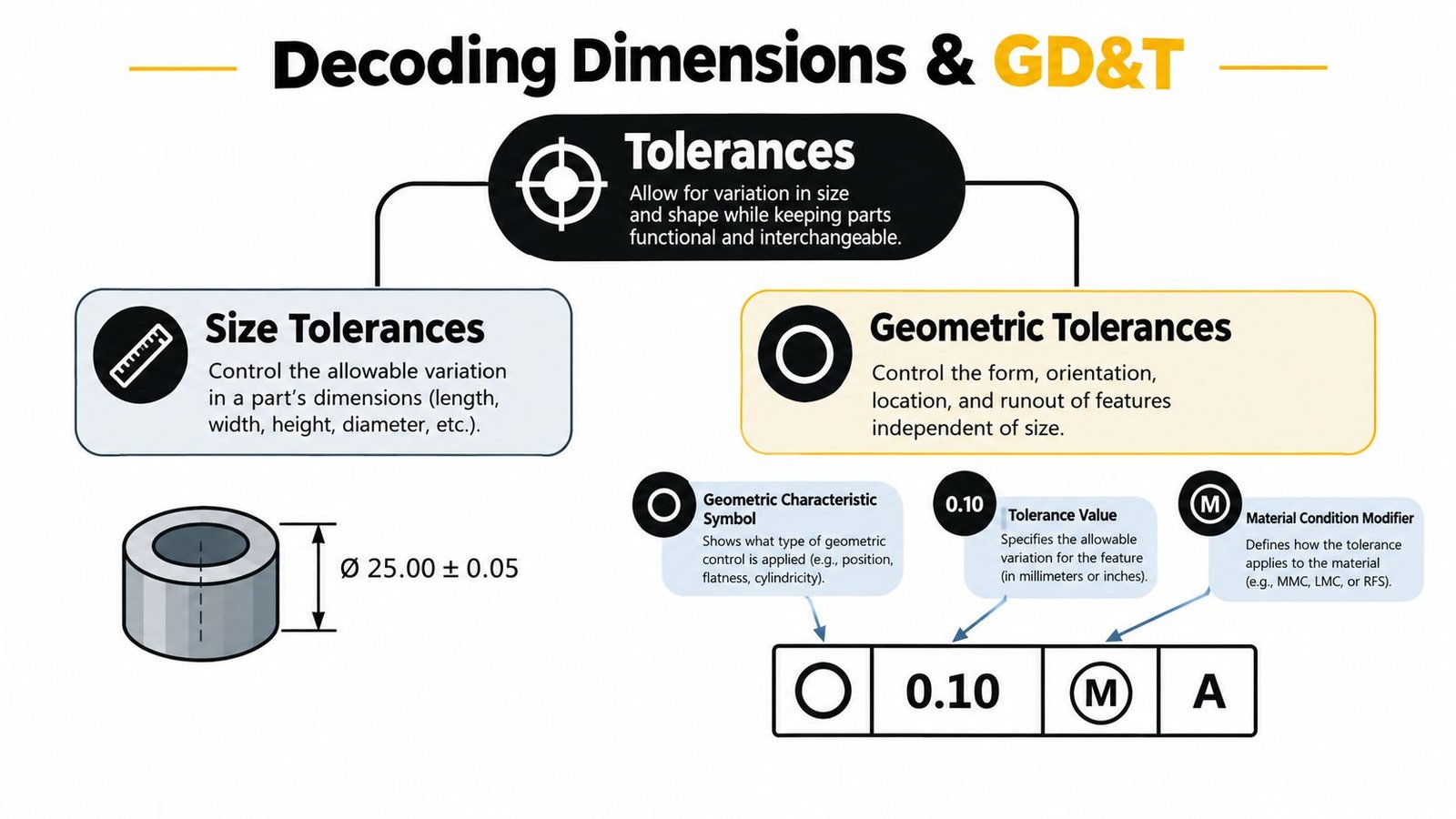
Size tolerances and geometric tolerances answer different questions. A size limit defines how large a feature may be. A geometric tolerance controls its shape, orientation, location, profile, or rotational behavior.
A hole can meet its diameter limits and still fail its position requirement. Measuring diameter alone won't establish whether its axis occupies the permitted location relative to the specified datum reference frame.
The distinction is easier to follow when the feature-control frame is separated into its elements.
Identify what the control actually limits
ISO 1101:2017 covers form, orientation, location, and run-out, with controls including straightness, flatness, circularity, cylindricity, parallelism, perpendicularity, position, and total run-out, as described in the ISO 1101 standard listing.
| Requirement family | Controls to recognize | Manufacturing question |
|---|---|---|
| Form | Straightness, flatness, circularity, cylindricity | Does the feature have the required shape? |
| Orientation | Parallelism, perpendicularity, angularity | Is its angular relationship acceptable? |
| Location | Position, concentricity, symmetry | Is the controlled geometry correctly located under the governing rules? |
| Run-out | Circular run-out, total run-out | Is variation during rotation acceptable? |
Profile controls also require attention to the defined geometry and any datum references. Don't select an inspection routine from the symbol name alone; the complete callout establishes the requirement.
Read the feature-control frame from left to right
Identify the geometric characteristic, then the tolerance value and zone definition, any material-condition modifier, and the datum references. Confirm whether the tolerance zone is diametrical rather than treating it as a radial allowance.
Datum precedence matters. Reversing the datum order can change the inspection meaning even when the numerical tolerance remains unchanged. ISO's documentation references distinguish datum systems from size and geometric tolerancing requirements in its technical product specification catalog.
Flatness, by contrast, controls form without necessarily locating the surface relative to another feature. That's why a flat surface isn't automatically an acceptable locating reference for every other requirement.
Maximum material condition and least material condition, commonly abbreviated MMC and LMC, need an explicit acceptance calculation where applicable. Don't ignore potential bonus tolerance, but don't add it indiscriminately either. Check the governing rules, actual feature size, and complete callout before accepting the result.
For mating components, individual conformity is only part of the assessment. Use tolerance stack-up analysis to evaluate how permitted variation combines across the assembly, rather than tightening isolated dimensions without checking the functional relationship.
Translating Drawings into Fixtures, and Inspection Plans
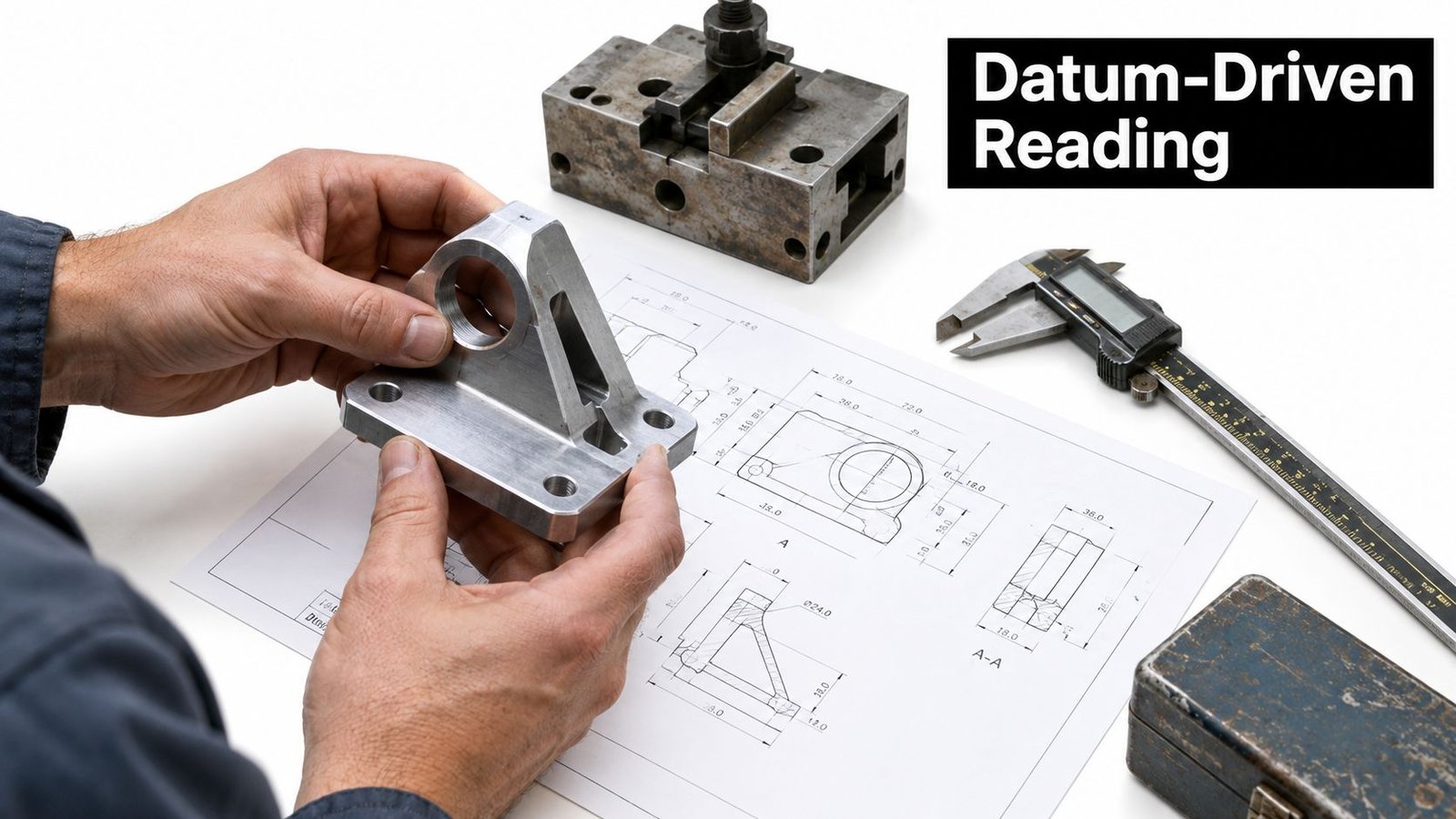
A useful planning exercise is a hypothetical medical-device housing with a bearing seat and mounting interface. The drawing review should establish how those interfaces work together before anyone chooses clamps, gauges, or workstation controls.
Inspection should connect the physical part to its complete drawing definition.
Build the setup around function
NIST's recommended GD&T workflow prioritizes function-controlling features, functional datums, datum-feature form, datum relationships, and then feature size and remaining form requirements. For production planning, use that sequence to organize the decisions:
- Confirm configuration: Establish the approved requirements before developing the setup.
- Identify functional interfaces: Determine what seats, aligns, seals, or supports the mating component.
- Interpret the specified datum frame: Reproduce the required locating relationships in workholding and inspection. If they don't reflect the intended function, raise the issue with engineering.
- Check each control: Connect its tolerance zone and modifiers to the planned process.
- Resolve conflicts: Review incompatible size, form, orientation, location, and run-out requirements before release.
For the housing example, the fixture should support the designated references while preserving access to the bearing seat. Clamp placement should be reviewed for possible distortion, not chosen solely for loading convenience.
That's the practical purpose of fixture design and manufacturing: converting a defined reference scheme into repeatable part location and usable production access.
The video below provides an additional visual reference for the tooling discussion.
Match the measurement to the requirement
Choose the inspection method after defining what must be demonstrated. A coordinate-measuring machine may suit complex geometric relationships; a surface plate and height gauge may suit accessible checks; a functional gauge may assess a defined assembly relationship. An in-process sensor should be selected for the characteristic it can detect, not because a signal is easy to collect.
The inspection plan should record ballooned characteristics, nominal values, limits, datum setup, instrument, and sampling rationale. For a semi-automated station, distinguish process-control signals from measurements that establish product acceptance.
Cost check: A tighter tolerance is only useful when it protects function. Otherwise, ask engineering whether the added machining and inspection burden is justified.
Any relaxation requires engineering approval and controlled documentation. Operators shouldn't substitute a looser requirement because the existing process struggles.
The earlier drawing-interpretation study surveyed 88 respondents in 2026: 79.55% reported drawing-related production delays, 73.86% scrap, 78.41% rework costs, and 72.73% material waste; only 26.14% rated graduate dimensional-tolerancing proficiency adequate and 14.77% rated standards-and-symbol compliance adequate. These are survey perceptions, not universal defect rates. They support a formal manufacturing-readiness review, not a prediction of your plant's losses.
When the Drawing Is Not the Only Source of Truth
A newer CAD file isn't automatically more authoritative than a released drawing. When a print, annotated model, and inspection dataset disagree, stop the handoff and establish which controlled definition governs. Don't let the machinist choose the model while quality follows the print.
BS 8888:2025 incorporates model-based definition through ISO 16792 and adds additive-manufacturing guidance, reflecting the use of annotated design data and machine-readable product-manufacturing information, as explained in BSI's overview of BS 8888:2025.
Compare the authority models
2D Drawing vs Model-Based Definition Authority
| Aspect | 2D Drawing | Model-Based Definition |
|---|---|---|
| Governing definition | Released drawing and referenced documents when designated authoritative | Released model, annotations, and associated data when designated authoritative |
| Human interpretation | Views, notes, dimensions, and callouts | Geometry, annotation views, and product-manufacturing information |
| Automation handoff | Requirements may need controlled transfer into programming systems | Semantic information can support machine-readable transfer |
| Revision conflict | Reconcile the print with models and supporting specifications | Reconcile the model with exports, inspection datasets, and supporting documents |
| Supplier fallback | Provide the complete controlled drawing package | Provide an approved representation suitable for the supplier's workflow |
The authority model should be explicit in the release process. A file timestamp, filename, or visually convincing model isn't a substitute for approval status.
Control the handoff and fallback
Distinguish human-readable annotations from semantic product-manufacturing information. A worker may see a tolerance on screen without the receiving software being able to interpret it as a structured manufacturing requirement. Verify the receiving workflow rather than assuming that a successful file import means complete data transfer.
For suppliers that require drawings, provide a controlled fallback tied to the governing definition. Establish its revision, scope, and approval, and identify any requirements that remain in associated documents. Use documented technical documentation standards to keep that relationship clear.
MBD doesn't remove the need for reading discipline. It shifts part of the review toward configuration control, software compatibility, and data quality. Engineering still needs to resolve conflicting requirements before manufacturing commits to a toolpath or inspection program.
A Practical Checklist and When to Bring in Mechanical Expertise
Before production release, confirm that the drawing has become an executable manufacturing plan:
- Configuration verified: Title block, released revision, notes, and governing documents agree.
- Geometry understood: Views, sections, and assembly information are reconciled.
- Controls interpreted: Datum setup and feature-control frames have an agreed meaning.
- Tooling defined: The fixture concept provides suitable location, support, and access.
- Inspection selected: Every required characteristic has a documented acceptance method.
- Review scheduled: Manufacturing, quality, and engineering have a release gate.
Escalate uncertainty before building equipment
Ambiguous notes, missing datums, contradictory tolerances, and unnecessarily restrictive specifications should trigger formal review. Bring in mechanical or automation expertise when the team can't connect a requirement to repeatable workholding, practical measurement, or an appropriate level of automation.
For medical-device production, FDA guidance defines process validation through objective evidence that a process consistently meets predetermined specifications. Drawing requirements should feed equipment settings, fixture qualification, inspection plans, and change control, consistent with the FDA process-validation guidance.
Disciplined reading is an inexpensive opportunity to prevent defects before equipment and production commitments make corrections harder.
System Engineering & Automation offers custom tooling, fixtures, manual and semi-automated equipment, integrated controls, and ongoing engineering support. Visit System Engineering & Automation to discuss your drawing package, production constraints, and inspection requirements before choosing a workstation or automation concept.