A production cell can look efficient right up until the same part starts arriving in inspection with slightly different hole locations, surface marks, or alignment errors. The machine is running, the toolpath hasn't changed, and operators are following the work instructions. The variation often begins underneath the part, where a generic vise, inconsistent clamp force, trapped chip, or weak datum scheme allows every reload to become a small experiment.
Custom workholding fixtures turn that hidden variation into an engineered process. They position each part against controlled references, resist cutting forces without distorting the workpiece, and create the access needed for the machining or assembly sequence. For operations managers, that means fewer interruptions and more usable capacity. For medical device manufacturers, it also means a clearer path to documented, repeatable, GMP-aware production.
The decision isn't whether a fixture can hold the part. It's whether the workholding system can support the required quality, throughput, safety, serviceability, and production volume without creating a new maintenance burden. The sections that follow treat fixture design as a production-optimization playbook, from locating and force control through validation, sensor verification, and cost-per-part analysis.
Table of Contents
- Why Custom Workholding Fixtures Make or Break Production
- Fixturing Principles That Ensure Repeatability and Accuracy
- Choosing Materials Clamping Methods and Tolerances That Fit Your Part
- From CAD and CAM to Prototype and Validation on the Shop Floor
- Proving ROI Throughput Gains and Cost per Part Improvements
- Deploying and Sustaining Custom Workholding Fixtures for Long Term Results
Why Custom Workholding Fixtures Make or Break Production
A familiar bottleneck starts with a part that's awkward to load. The operator seats it in a standard vise, tightens the handle by feel, clears a few chips, and begins the cycle. The first component passes. The next one is close but needs rework. By the end of the run, inspection is sorting parts, the machine is waiting, and the production team is debating whether the issue is tooling, programming, material, or operator technique.
Often, the fixture is the process variable.
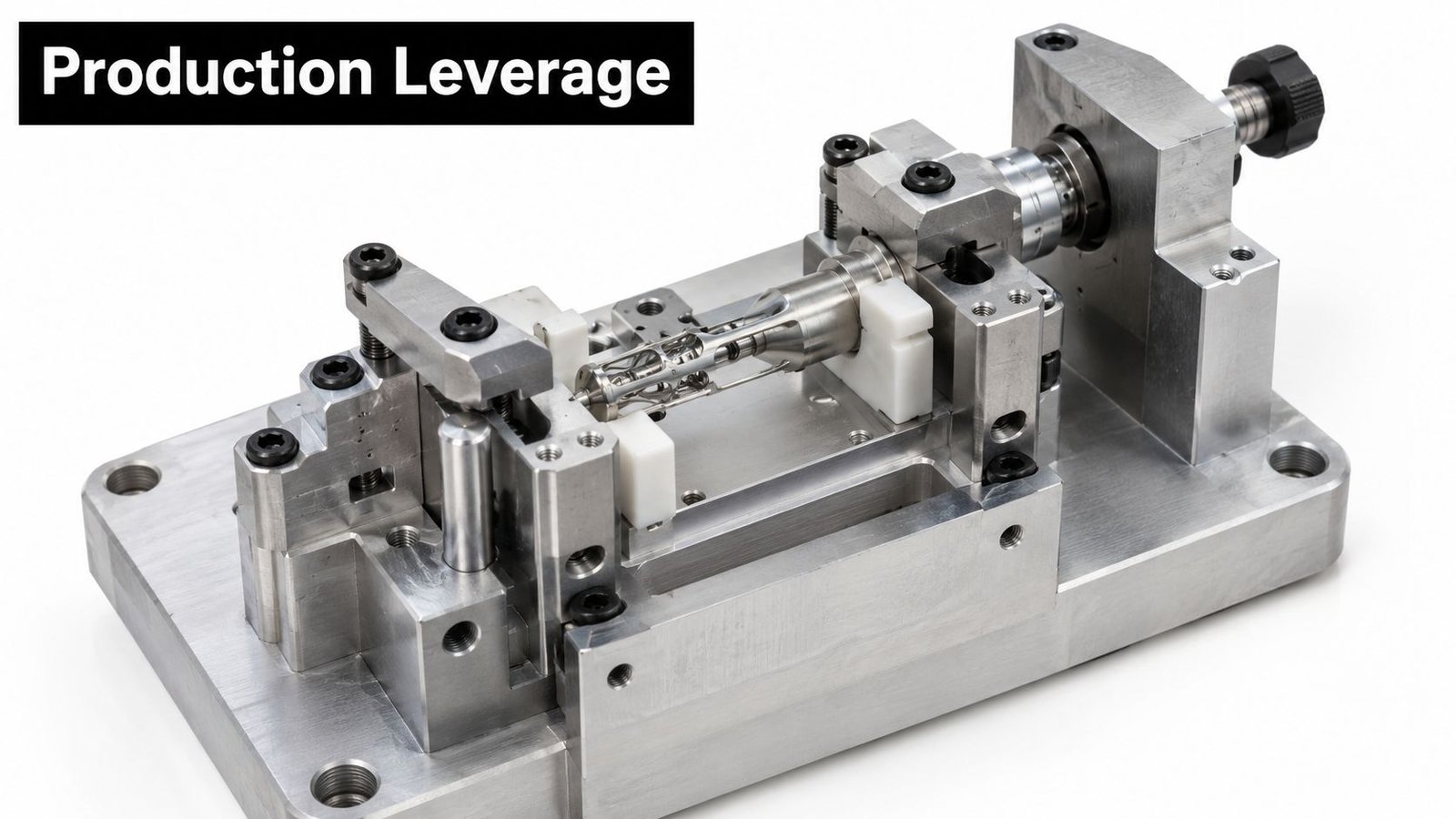
A standard vise can be the right answer for a rigid, accessible part with forgiving tolerances. It becomes a poor choice when the component has irregular geometry, thin walls, multiple machining faces, limited clamp access, or datums that need to return to the same machine coordinate position. Custom workholding fixtures address those conditions by matching supports, locators, clamps, and clearance to the actual part and process.
The distinction between accuracy and repeatability matters here. Accuracy describes how close a placement is to the intended nominal position. Repeatability describes how tightly repeated reloads cluster together. A fixture can place one part correctly and still fail production if the next reload lands somewhere else.
Production rule: A fixture earns its place by making the next part behave like the last part, not by holding one part tightly.
Market activity reflects how central this category remains to manufacturing. The global workholding devices market was valued at USD 7.35 billion in 2025 and is projected to reach USD 12.68 billion by 2032, with an implied 8.1% CAGR during 2026–2032, according to Strategic Market Research's workholding devices analysis. Fixtures represented 18.0% of 2025 revenue, or about USD 1.323 billion, and the source projected fixtures to be the fastest-growing product type at a 9.5% CAGR, linked to five-axis machining, robotic loading, and complex aerospace parts.
When standard workholding stops being economical
Custom becomes sensible when the cost of variation exceeds the cost of designing and maintaining a solution built for the task. That calculation includes more than scrap. It includes setup labor, inspection time, machine waiting, damaged tools, operator-dependent adjustments, and the lost capacity created by repeated changeovers.
A broad estimate placed the global workholding market at about USD 9.7 billion in 2024, with projected growth to roughly USD 15.2 billion by 2034 at a 4.6% CAGR. The same global workholding product market estimate put North America at about 40% of 2024 revenue and estimated that vises and clamps together represented about 40% of the market. Those figures reinforce a practical point: conventional devices remain foundational, but they don't automatically solve an application-specific production problem.
For semi-automated stations, the fixture must also communicate with the process. A robot needs a predictable load position. A technician needs a clear inspection reference. A quality team may need evidence that the part was present and clamped before the cycle began. That's where a well-designed fixture becomes part of the service and production system, rather than a passive block of metal.
Fixturing Principles That Ensure Repeatability and Accuracy
Start with the datum scheme, not the clamp catalog. A clamp creates force. A locator establishes position. If those functions are confused, operators may produce a part that feels secure but isn't located consistently.
The most widely used foundation is the 3-2-1 locating principle. Three supports establish the primary locating surface, two locators establish the secondary direction, and one locator controls the remaining direction. This arrangement removes the necessary degrees of freedom without unnecessarily trapping the workpiece.
Build the locating scheme around the part's functional datums
The primary supports should contact a surface that can carry the workpiece without rocking or flexing. Secondary and tertiary locators should reference surfaces that matter to the finished part, not merely surfaces that are convenient to reach. If the part's hole pattern must align with a machined edge, the locating strategy should relate those features through the same datum logic used on the drawing.
Clamps should push the part into the locators. A clamp that pulls the workpiece away from a reference, or creates a twisting moment before the part is seated, makes the operator's loading motion part of the tolerance stack. The workholding and fixture design guidance on 3-2-1 locating also emphasizes chip control and poka-yoke loading. A chip beneath a locator changes the seated position, while a poka-yoke feature prevents the wrong orientation.
Use practical checks before releasing the design:
- Confirm contact order: The part should seat on primary, secondary, and tertiary references before the clamps reach final force.
- Control chip paths: Add reliefs, wipers, air blast access, or inspection points so debris can't hide beneath a locating surface.
- Error-proof orientation: Use an asymmetric pin pattern, keyed feature, or hard stop that makes incorrect loading difficult.
- Protect the part: Put clamp force over supported regions, not over thin walls, unsupported ribs, or finished surfaces.
Measure repeatability instead of assuming it
A reload study is straightforward. Locate the same workpiece, clamp it, and measure selected features. Remove it, reload it, clamp it again, and repeat the measurement under the same setup conditions. The spread between those readings is the fixture's practical repeatability for that part and process.
That test is more useful than a one-time alignment check because it exposes operator variation, seating problems, clamp sequence effects, and debris sensitivity. It also separates fixture behavior from machine accuracy. A fixture may consistently return a part to the same offset position, which indicates good repeatability even if the fixture's nominal location still needs correction.
For manual and semi-automated stations, document the loading motion in the work instruction. Show where the operator applies seating pressure, which clamp closes first, what surfaces must be clean, and how the poka-yoke feature is checked. A fixture that depends on tribal knowledge will perform differently across shifts.
Choosing Materials Clamping Methods and Tolerances That Fit Your Part
A thin-walled medical component, a rigid billet, and a finished cosmetic housing can run on the same machine yet require different fixture materials and clamping methods. Start with how the part reacts to force, where it can be supported, and what the process must leave accessible.
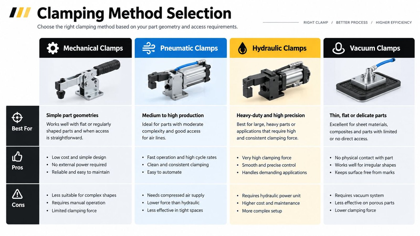
Mechanical clamps are a practical first choice when the part has strong clamping surfaces and operators need quick access. They are durable and easy to inspect, but hand torque introduces variation. Clamp position can also shift, and difficult loads may receive more force than simple ones.
Pneumatic clamps improve cycle consistency in semi-automated cells, especially when a controller sequences several clamps. They require clean, reliable air, dependable actuation, and a way to detect incomplete movement. Hydraulic clamps provide higher force in a compact package, but leaks, guarding, maintenance, and service access must be addressed during fixture design.
Vacuum clamping suits parts with broad, reasonably continuous surfaces where mechanical clamps would obstruct tool access or mark the finish. Interrupted, porous, contaminated, or undersized sealing surfaces reduce its margin against cutting loads.
Match fixture construction to stiffness, weight, and service needs
Steel bases provide stiffness and wear resistance. Aluminum lowers fixture mass and makes manual handling easier, but high-wear locating surfaces may need hardened inserts or replaceable bushings. Polymer pads, soft jaws, and sacrificial contacts protect finished surfaces and conform to sensitive geometry. They also need inspection intervals and replacement plans.
Fixture mass should match the station. A base that technicians must remove for cleaning or changeover should not be heavier than necessary. A base exposed to vibration, long overhangs, or high cutting loads needs enough stiffness to hold position. Balance rigidity with access, lifting, maintenance, chip evacuation, and the actual force path through the part.
Tolerance decisions should follow function rather than habit. A micron-class positioner fixture reported stiffness of 1050.5 N/μm and repeated positioning accuracy of ±0.48 μm in X, ±0.45 μm in Y, and ±0.49 μm in Z, with positioning accuracy specified below 1 μm, as documented in the published high-precision fixture study. That performance is not the default requirement for every production fixture. Other multipoint flexible-fixture experiments reported clamping errors in the 0.01–0.06 mm range, reinforcing the need to match fixture architecture and part compliance to the tolerance class.
Treat clamp force as a controlled process input
Thin walls can distort when a clamp is tightened beyond what the support scheme can absorb. One study reported that 20%–60% of machining errors in thin-walled parts can be caused by clamping, so force control and loading sequence belong in the process design. Use the minimum force that prevents lift, slip, and vibration, then verify the result with trial-part metrology.
Force selection should account for contact area, friction, cutting direction, wall thickness, and support beneath the clamp. For GMP-aware or semi-automated lines, a pressure switch, force sensor, or clamp-position check can confirm that the intended condition exists before machining begins. A sensor does not replace a sound locator layout, but it can prevent an incomplete clamp or abnormal load from reaching the tool.
If the part springs back after release, the fixture may have produced a stable machining condition that was wrong for the free state. A lower-force clamp, broader pad, intermediate support, or different machining sequence may correct the result more effectively than just adding rigidity.
Use a tolerance stack-up analysis before finalizing locator sizes and contact positions for complex tolerances. It separates a genuine fixture requirement from variation that the machine, tool, inspection method, or upstream process can absorb. That distinction keeps the fixture accurate without making it unnecessarily expensive or difficult to service.
From CAD and CAM to Prototype and Validation on the Shop Floor
A fixture should be validated as a force-and-location system, not just admired as a clean CAD assembly. The most reliable workflow carries the part, datums, clamp order, tool access, and inspection plan through every handoff.
Model the way the fixture will actually load
Begin by modeling the clamping sequence, locator layout, and contact geometry. Show the order in which supports engage, locators seat, clamps close, and sensors confirm the load. A static screenshot of nominal contact points won't reveal whether the first clamp shifts the part before the second clamp seats it.
One experimental validation of a clamping-sequence model found average prediction errors of 22.1% for workpiece location and 29.9% for reaction forces, demonstrating that sequence choice materially affects fixture performance. The published clamping-sequence research supports treating clamp order as a design variable rather than an operator detail.
Run a simulation pass that examines force redistribution and likely deformation. Then check the fixture against the drawing's datum scheme and tolerance requirements. The critical question isn't whether every CAD face touches another CAD face. It's whether the actual part, with its actual surface variation, friction, compliance, and debris exposure, will settle where the process expects it to settle.
Complete the CAM and clearance review before fabrication
Bring the fixture model into CAM. Check the toolpath, probing approach, spindle orientation, clamp envelopes, chip evacuation, and collision risk. A locator that provides excellent repeatability but blocks a finishing tool still fails the process.
At this stage, test maintenance access as well. Can a technician remove a worn pad without taking the whole station apart? Can an operator clean the primary datum without reaching into a pinch point? Can the fixture be lifted, stored, and reinstalled without losing its reference?
The design and fabrication handoff should include:
- Controlled datum references: Identify the surfaces used for fixture manufacture, machine setup, part location, and inspection.
- Defined clamp sequence: Specify the actuation order and the expected seated condition before cutting.
- Replaceable wear items: Use inserts, bushings, pads, or soft jaws where repeated contact will change the locating condition.
- Inspection features: Add access for gauges, probes, visual checks, and cleaning.
- Part-presence logic: Define what must be true before the machine can start.
A practical fixture design and manufacturing partner can connect these details from concept through drawings and build. SEA's fixture design and manufacturing services are one example of an engineering path that includes custom tooling and fixtures within broader manufacturing solutions.
Prototype, trial-cut, and measure the first setup
Physical verification is mandatory after the first setup. Load a representative part, inspect seating, run the planned clamp sequence, and check for lift or movement. Then make a controlled trial cut and measure the result against the first located position or the theoretical CAD position, depending on the validation plan.
Literature on fixture-quality control identifies workpiece deformation, clamp force, friction, and cutting force as major drivers of location error. That's why nominal CAD contact points can mislead. The fixture must be tested under the force conditions that matter in production, not only under an unloaded assembly check.
Use the validation record to capture what was loaded, how it was clamped, what was measured, and what changed. If the first setup needs a locator adjustment, update the controlled drawing and work instruction together. Otherwise, the shop may correct the hardware while the documentation continues directing operators to the old method.
The process can be summarized as follows: simulate, tolerance-check, trial-cut, measure, correct, and release.
The following embedded video provides another visual reference for fixture validation and machining setup:
Proving ROI Throughput Gains and Cost per Part Improvements
A fixture business case should begin with the constraint, not the equipment price. If the production team loses time during loading, changeover, inspection, or manual adjustment, the fixture should be designed to attack that specific loss.
Custom fixtures can reduce setup and changeover time by eliminating repeated layout work and operator positioning decisions. They can also expose more of the part to the tool, reducing the need for additional setups. The value appears as more stable output from existing equipment, not merely as a nicer-looking fixture.
One industry publication states that tailoring workholding to the exact component can help manufacturers meet tight tolerances, shorten cycle times, achieve the lowest cost per part, and free additional capacity. The same custom workholding design discussion reports a concrete gain from integrating the pallet directly onto the fixture base. That change doubled the available workholding space and significantly increased machine productivity.
Calculate the value in operational terms
Separate the business case into recurring and one-time effects:
- Recurring time savings: Fewer manual adjustments and shorter loading or changeover activities.
- Quality savings: Less scrap, rework, sorting, and investigation caused by inconsistent positioning.
- Capacity recovery: More productive machine time from better access and reduced waiting.
- Labor stability: Lower dependence on highly experienced operators for routine seating decisions.
- Serviceability: Faster replacement of wear components and clearer troubleshooting when a sensor or clamp fails.
For semi-automatic lines, this often represents the practical middle ground. Pneumatic or hydraulic actuation can standardize the physical clamp action while an operator still handles loading and visual checks. Fully automated loading may be justified when volume, labor constraints, safety requirements, or traceability demand it. A modular manual fixture may be the better choice when product mix changes frequently.
| Lever | What It Improves | When It Matters Most |
|---|---|---|
| Setup and changeover control | Reduces repeated positioning and manual adjustment | Multiple setups, recurring jobs, or frequent product changes |
| Machining access | Exposes more features in one secure load | Complex geometry, five-axis work, or deep machining access |
| Force consistency | Limits distortion and operator-to-operator variation | Thin walls, flexible components, and sensitive finished surfaces |
| Part-presence verification | Prevents cycles from starting on an incomplete load | Semi-automated cells and high-value components |
| Capacity utilization | Converts waiting and handling time into productive machine time | Constrained equipment and growing production demand |
Track the cost per accepted part, not only the machine cycle. A fixture that adds hardware cost but removes recurring setup variation may be economical even when the part volume isn't high. Conversely, a dedicated fixture can be the wrong investment if the design changes often or the line needs broad product flexibility.
Use production cost analysis to connect fixture decisions to labor, quality, throughput, maintenance, and capacity rather than treating the fixture as an isolated purchase.
Deploying and Sustaining Custom Workholding Fixtures for Long Term Results
A fixture doesn't stay repeatable by itself. Locating surfaces wear, clamps loosen, pads collect chips, seals age, and operators find shortcuts when the intended loading motion is awkward. Sustained performance requires a control plan that treats the fixture as production equipment.
The largest gap in many workholding programs is verification before machining. Teams often confirm that a fixture can hold the part during commissioning, then assume clamp security remains correct forever. Production needs evidence that the part is present, seated, and clamped before the tool enters the material.
Add verification where failure can still be prevented
Pressure sensors can confirm that a pneumatic or hydraulic clamp reaches the expected condition. Vacuum sensors can alarm or stop the cycle if a part loses rigidity or the vacuum state changes. These controls shift workholding from static holding power to in-process risk control, particularly for thin-wall or high-value parts. Industry coverage of sensor-based fixturing identifies pressure sensing for consistent clamping force and vacuum sensing that can alarm or shut down when part rigidity is lost.
Capture the result in the production record when the process requires it. A GMP-aware line should define which fixture checks are critical, who reviews them, how failed loads are contained, and when a fixture is removed from service. The record might include clamp-state confirmation, part-presence status, inspection results, maintenance actions, and revision-controlled work instructions.
Put maintenance and operator behavior on the same plan
Use a short, visible deployment checklist:
- Clean: Remove chips and residue from primary supports, pins, seats, and vacuum surfaces.
- Inspect: Check wear pads, locator edges, bushings, clamp contact points, hoses, and sensors.
- Verify: Confirm the part seats correctly and the machine receives the expected clamp and presence signals.
- Standardize: Define loading pressure, clamp order, torque where applicable, and approved contact surfaces.
- Measure: Perform scheduled reload checks against the established datum and repeatability method.
- Escalate: Stop production when a part lifts, a sensor disagrees with the physical condition, or a critical locator shows damage.
Train operators on why each action matters. “Clean the locator” is easier to follow when the team understands that one chip can change the seated position and send variation downstream. Service technicians also need access to spare wear components and clear replacement criteria.
System Engineering & Automation provides custom tooling, fixtures, semi-automatic systems, integrated controls, installation, commissioning, and ongoing support for manufacturers that need a workholding solution tied to production goals and budget. For a fixture program that must improve throughput while supporting quality, safety, and service requirements, System Engineering & Automation can help evaluate the part, process, automation level, and validation needs before the design is released.