
At 02:14, the line stops between two production cycles. The HMI shows a servo overcurrent, the operator reports that the previous cycle sounded normal, and a tray of in-process product is waiting beside the station. One technician reaches for a spare drive, another checks the mechanical assembly, and production wants the reset button pressed. On a semi-automatic line, that pressure is familiar. It's also where an undocumented guess can turn a minor fault into repeated downtime, a quality event, or both.
A useful equipment troubleshooting guide must do more than list possible causes. It should help operators, maintenance technicians, engineers, and quality personnel separate mechanical, electrical, software, process, and GMP-related faults before anyone replaces a part or changes a parameter. The practical objective is simple: restore safe production, verify the result, and leave behind a diagnostic record that makes the next intervention faster.
Table of Contents
- Why Production Equipment Fails When You Least Expect It
- The First 30 Minutes on the Floor
- From Symptom to Root Cause Without Guesswork
- Splitting Process Faults from Control Faults on Semi-Automatic Lines
- Diagnostic Tools That Speed Up the Fix
- Escalation Rules, Verification, and the Paper Trail That Pays Off
- Turning One Breakdown Into Fewer Next Time
Why Production Equipment Fails When You Least Expect It
The 02:14 stoppage rarely begins at 02:14. A guide roller may have developed slight resistance during thermal cycling. Lubricant may have degraded gradually. A software update may have changed the timing between a sensor and an actuator without producing an obvious alarm. Each drift looks harmless in isolation, but together they narrow the machine's operating margin until one normal cycle exposes the weakness.
That's why operators often describe a failure as sudden even when the underlying condition has been developing for some time. A hard failure, such as a blown fuse or broken coupling, announces itself clearly. A soft failure is different. The machine still runs, but it misfeeds occasionally, takes longer to reach position, produces inconsistent torque, or requires an operator intervention that wasn't needed before.
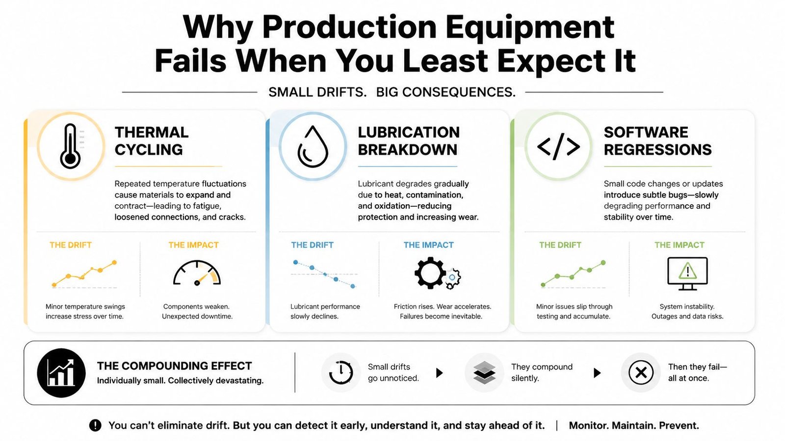
Small drifts create large symptoms
On a hybrid line, the operator may compensate for a mechanical change by repositioning a component. That adjustment can hide the original issue while creating a new alignment problem. A controls technician may then alter a timer to accommodate the changed motion, and the line appears stable until a different product, shift, or temperature exposes the interaction.
This is the failure pattern generic checklists miss. They name components, but they don't always capture the sequence of changes that led to the symptom. A practical guide should record what changed, when it changed, which operating mode was active, and whether the fault appeared during startup, steady production, changeover, or recovery.
Practical rule: Treat an unexpected stop as evidence of a changing system, not proof that the last alarmed component is defective.
The economic stakes explain why structured troubleshooting matters. One industry summary reports that the world's 500 largest companies lose about 11% of annual revenue to unplanned downtime, equivalent to roughly $1.4 trillion, compared with $864 billion in 2019. Those figures are reported in a 2025 manufacturing maintenance industry summary.
A disciplined process turns the event into more than a repair. It captures the symptom, evidence, suspected cause, corrective action, and verification result. That record gives the next maintenance team something better than memory and helps manufacturing organizations provide more reliable production support to their customers.
The First 30 Minutes on the Floor
The first response should reduce uncertainty, not create more of it. Start by confirming the exact symptom. Is the capper failing to feed, refusing to index, stopping on an E-stop input, or reporting a torque fault after the actuator reaches position? “The machine is down” isn't specific enough to guide a test.
Then secure the line. Follow the site's lockout and tagout requirements before entering hazardous areas, reaching into tooling, or inspecting stored energy. In GMP production, segregate in-process product according to the site procedure before troubleshooting changes the equipment state or makes product disposition harder to determine.
Use the symptom as the starting point
Talk to the operator before opening a panel. Ask what happened immediately before the stop, whether the fault repeats in the same step, whether the operator had to intervene during earlier cycles, and whether a changeover, cleaning activity, material lot, or recipe selection preceded the event.
Use the answer to select the first isolation path:
- Misfeed on a capper: Check the part presentation, guide rails, fixture seating, and sensor state without adjusting anything. Confirm whether the sensor sees the part and whether the PLC receives that input. If the part is present and the input is correct, follow the sequence toward the actuator and interlock instead of replacing the sensor immediately.
- Phantom E-stop: Confirm the HMI diagnostic state and inspect the E-stop circuit according to the approved electrical procedure. Check whether the safety input drops consistently, intermittently, or only during a specific motion. Don't bypass the circuit to keep production moving.
- Servo overcurrent: Look for a mechanical bind, obstruction, abnormal coupling resistance, and recent position or recipe changes. After safe isolation, compare commanded motion with actual motion and review the drive alarm history before deciding that the servo or drive needs replacement.
A half-split or unit-substitution test can narrow the search, but only after the machine state and safety conditions are controlled. Test one variable at a time, use a known-good module only when the substitution is authorized, and record the result immediately.
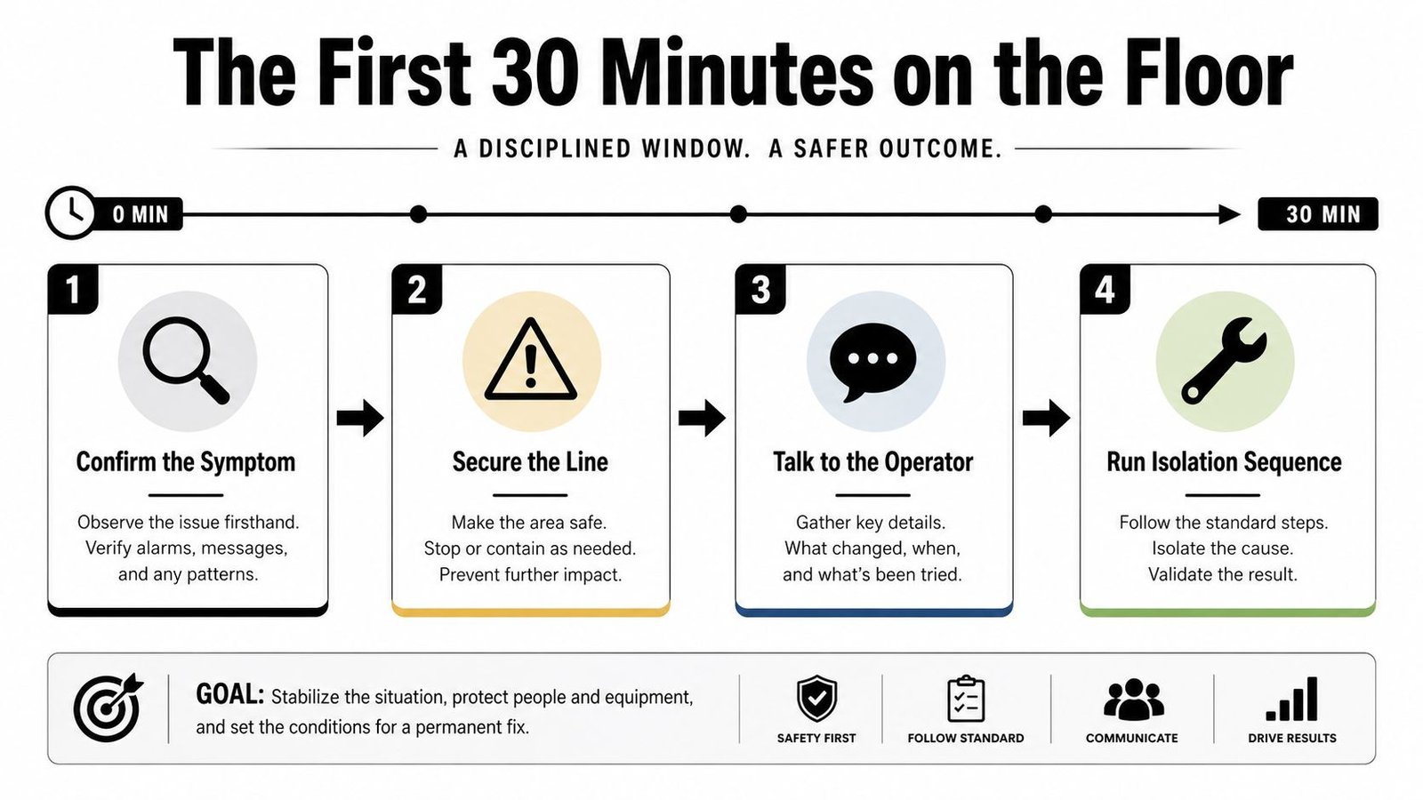
The early sequence should look like this:
- Confirm the symptom: Reproduce or characterize the fault without changing settings.
- Secure the line: Apply safety controls and protect affected product.
- Talk to the operator: Capture timing, sounds, interventions, and recent changes.
- Run isolation tests: Separate the fault by function, signal path, and operating mode.
What should you skip? Random component swaps, unapproved parameter changes, repeated resets that erase useful evidence, and mechanical adjustments made before the original condition is documented. A reset may return the line temporarily, but it doesn't prove the fault is gone.
From Symptom to Root Cause Without Guesswork
Root cause work fails when the team treats the last visible alarm as the diagnosis. The better approach is to define the symptom precisely, collect objective evidence, map the event sequence, localize the failed function, and then test the most plausible causes one at a time.
Consider intermittent torque-fault alarms on a semi-automatic capper. The first assumption might be a failing servo because the drive reports an overcurrent condition. A disciplined check compares the alarm timestamp with motion data, inspects the cable path, checks connectors, and observes whether the fault appears at a repeatable position or under a specific flex condition. If the servo performs normally with a controlled test and the signal becomes unstable when the cable moves, a degraded cable becomes a more defensible cause than the servo itself.
Adapt 5 Whys to hybrid systems
The failure mode analysis resource can help teams organize possible failure mechanisms, but the investigation still needs evidence from the actual machine. Apply 5 Whys across layers rather than asking only why the component stopped.
- Why did the capper generate a torque fault? The drive detected abnormal current.
- Why was current abnormal? Motion resistance or feedback became unstable.
- Why did the condition appear intermittently? The cable or connection changed state during movement.
- Why was the cable vulnerable? Routing, strain relief, or flex protection was inadequate.
- Why did the design allow that condition? The installation or maintenance standard didn't control the cable's service environment.
The point isn't to force five answers. The point is to continue until the action is within the organization's control and can be verified. A replacement servo may clear the alarm, but it won't correct a cable-routing weakness.
| Heuristic | What It Reveals | Pitfall It Prevents |
|---|---|---|
| Divide the signal or motion loop | Whether the fault is before or after a test point | Searching the entire machine at once |
| Use a controlled known-good substitution | Whether a module follows the fault | Replacing parts based on alarm labels |
| Anchor evidence to the alarm timestamp | What happened immediately before the stop | Trusting memory after repeated resets |
| Ask 5 Whys across mechanical, electrical, and software layers | Whether the failure is systemic | Treating the failed component as the root cause |
| Test one variable at a time | Which change affected the symptom | Creating new symptoms during diagnosis |
A durable record should state the failure mode, probable cause, corrective action, and verification outcome. That information belongs in the CMMS or approved maintenance record, not only in a technician's notes.
Splitting Process Faults from Control Faults on Semi-Automatic Lines
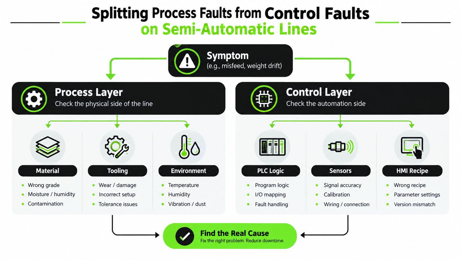
A misfeed, weight drift, or intermittent stop can originate in the process or in the control layer. The symptom alone won't tell you which one is responsible. Semi-automatic systems make this harder because an operator, a fixture, a material presentation step, and an automated sequence all contribute to the same cycle.
Start with a forced-step test under approved conditions. Bypass the operator station only through the machine's authorized manual or maintenance mode, then command each actuator directly through the PLC. Confirm the actuator's response, feedback, timing, and physical movement.
Test the control layer
If an actuator responds correctly under direct manual command but fails during automatic operation, the mechanical hardware may not be the primary fault. Investigate the PLC sequence, permissive logic, sensor transitions, interlocks, and HMI recipe loading.
For example, a clamp may close when commanded manually but remain open in automatic mode. Check whether the PLC sees the part-present signal, whether the recipe calls for the expected clamp state, and whether an interlock is withholding the command. Do not change the logic or recipe just to make the cycle run. First capture the original state and escalate the proposed change through the site's change-control process.
Validate the process layer
The process-side check should examine incoming material specifications, fixture integrity, tooling condition, and ambient conditions against the approved operating range. A cap that fails to seat may reflect variation in the component, a worn nest, contamination, or a control sequence that releases the part too early.
Use a split-test record with fields for:
- Observed symptom: What happened and at which cycle step.
- Control result: What the PLC, sensors, actuator, and HMI showed.
- Process result: What material, tooling, and environment showed.
- Product status: Which in-process product was segregated or assessed.
- Deviation reference: The applicable deviation or event identifier.
- Decision: Whether production remains stopped, resumes under approved controls, or escalates.
Apply a GMP gate before restart
In regulated manufacturing, a technically successful repair may still be incomplete if the event isn't documented and reviewed. GMP guidance calls for preventive maintenance schedules for equipment affecting product quality or safety, along with records such as maintenance procedures, IQ/OQ/PQ qualification documents, calibration certificates, change-control records, and personnel training records. These expectations are summarized in GMP equipment maintenance guidance.
Any change to recipe parameters, tooling geometry, or interlocks should trigger a safe-stop decision and QA review before restart. A fix that isn't tied to the deviation record can complicate batch documentation, product disposition, and later investigation.
Diagnostic Tools That Speed Up the Fix
A diagnostic tool earns its place by shortening the path from symptom to fault. Choose it for the question it can answer, not because it appears advanced. On a semi-automatic or hybrid line, observation, listening, a flashlight, and a review of the machine state often expose the first useful clue.
A quality multimeter can identify dead sensors, missing supply voltage, open circuits, and wiring faults that PLC diagnostics may show only as a missing input. It cannot explain every intermittent fault. A voltage reading taken without understanding the circuit can mislead, so define the test condition and the hypothesis before taking measurements.
Match the instrument to the symptom
A thermal camera can reveal an overheated drive, bearing, contactor, or connection before the component trips. Its value drops inside an enclosed panel or where surface emissivity and access make the image unreliable. PLC, drive, and vision-system logs can expose sequence errors, timing faults, and parameter drift that field instruments cannot show. Interpreting them requires familiarity with structured text, timestamps, and state transitions.
Vibration sensing suits rotating equipment with bearing or balance concerns. On a linear actuator, it may produce noise without distinguishing a mechanical bind from a control issue. A manometer can answer a pneumatic question more directly than a complex data logger.
| Tool | Catches Well | Misses / Misleads On |
|---|---|---|
| Multimeter | Dead sensors, open wires, missing voltage, continuity issues | Fast intermittent faults without a captured test condition |
| Thermal camera | Hot drives, bearings, contactors, and connections | Enclosed panels, poor access, misleading surface temperatures |
| PLC and vision logs | Sequence errors, timing faults, recipe or parameter drift | Mechanical conditions that aren't represented in the data |
| Vibration analyzer | Bearing wear and rotating-equipment changes | Linear motion, loose process parts, and unrelated machine noise |
| Oscilloscope or scope meter | Signal quality, noise, and transient behavior | Questions that require physical inspection or process observation |
A tiered kit keeps the response practical:
- Basic: Multimeter, manometer, inspection light, flashlight, and mechanical stethoscope.
- Intermediate: Thermal camera, oscilloscope, and tachometer.
- Advanced: Data logger, vibration analyzer, and remote HMI access.
The machine monitoring software can connect operating history with maintenance events, but it does not replace direct observation or the separation of mechanical, electrical, software, and GMP-quality faults. Start with the cheapest safe check that can disprove the leading hypothesis. Move to specialized equipment only when the evidence supports it, and record the test condition so another technician can reproduce the finding.
Escalation Rules, Verification, and the Paper Trail That Pays Off
A machine that runs after a reset hasn't necessarily been repaired. Verification must demonstrate that the original failure mode is controlled under the conditions that matter for production and quality.
Set role boundaries before an event occurs. The operator can perform an approved reset and report the symptom. The technician can secure the equipment and isolate the fault. An engineer should approve the technical root cause and repair strategy. QA should review corrective action where product quality, validated parameters, records, or GMP controls may be affected.
Verify the repair under production conditions
A practical verification protocol should include a functional test at defined speeds, three consecutive good units, a parameter check against the validated setpoint, and a documented re-check of GMP-critical characteristics such as torque, weight, and seal integrity. These checks should reflect the actual failure mode. A cycle without an alarm isn't enough if the original issue involved product acceptance.
Escalate when the fault repeats, when the cause remains uncertain, when a safety circuit or validated parameter is involved, or when product may have been affected. GMP maintenance decisions should be multidisciplinary and risk-based. Guidance on common GMP maintenance missteps emphasizes participation from engineering, maintenance, and quality assurance, rather than relying only on time-based maintenance.
Record enough for the next investigation
The maintenance record should capture:
- Time of event: Include the first observed symptom and subsequent resets or interventions.
- Suspected cause: Separate evidence from assumptions.
- Actions taken: Include inspections, tests, adjustments, and approvals.
- Parts replaced: Record part identity and reason for replacement.
- Lots affected: Identify product and material lots under the applicable procedure.
- Deviation reference: Tie the event to the approved quality record.
- Signature chain: Identify the operator, technician, engineer, and QA reviewers involved.
Closing a ticket after the first good unit is a common mistake. So is skipping documentation because production pressure is high. Both choices leave the next shift without the evidence needed to recognize a recurring failure.
Enter the completed event into the CMMS and connect it to the asset history. A documented cause and verification outcome can then support recurring-fault review, mean-time-between-failure reporting, and planning for the next maintenance window.
Turning One Breakdown Into Fewer Next Time
The value of troubleshooting appears after the line is running again. A single event becomes useful only when the organization converts it into a controlled prevention action. Tag the failure mode consistently, then evaluate it against production impact, GMP risk, recurrence, and how easily the condition could have been detected.
Not every correction deserves a permanent redesign. A loose connection that was isolated, repaired, and protected may need a targeted inspection added to the maintenance routine. A repeated cable failure, recurring sensor contamination, or persistent recipe mismatch points toward a broader action involving design, installation, training, or controls governance.
Promote the right corrections
Use practical decision criteria:
- Frequency: Has the same symptom appeared repeatedly in the asset history?
- Severity: Could the failure affect safety, product quality, or a major production commitment?
- Detectability: Can an operator or technician identify the condition before the line stops?
- Control: Can the organization prevent recurrence through design, inspection, software control, or training?
- Verification: Can the corrective action produce an observable, documented result?
A recurring failure should lead to a review of the preventive maintenance task, spare-parts strategy, standard operating procedure, and operator training matrix. It may also justify a design review of fixtures, conveyors, indexing tables, torque-presenting tools, sensors, or light-cobot interfaces.
Let evidence shape the next improvement
Trend data should carry more weight than shift-floor anecdotes. Review the asset history for repeated symptoms, similar alarm timestamps, parts replaced without durable resolution, and differences between shifts or product configurations. Those patterns can guide FMEA updates, spare-parts rationalization, cross-shift handoffs, and changes to inspection points.
Predictive methods have a role when the failure mode produces a measurable precursor. A structured predictive maintenance implementation approach should begin with the asset, failure mode, available signals, and decision that the data will support. Adding sensors without a response plan only creates another stream of information for the team to ignore.
Operators and technicians should be treated as contributors to the reliability system, not merely as people who report breakdowns. Their observations can identify early changes in sound, resistance, alignment, material presentation, or HMI behavior. When those observations enter the CMMS and feed the next FMEA revision, the next failure may be prevented, detected earlier, or isolated with less disruption.
System Engineering & Automation provides semi-automatic and hybrid manufacturing solutions, including custom tooling, fixtures, integrated controls, installation, commissioning, maintenance, and ongoing support. If your production line needs a more disciplined approach to fault isolation, safe restart, or GMP-aware equipment improvement, visit System Engineering & Automation to discuss your production and service requirements with the engineering team.