
You're usually not looking at die and moulds because you're curious about tooling terminology. You're looking because production isn't behaving the way the business model says it should. Scrap is creeping up. Operators are compensating for part variation. A robot cell that looked reliable during trials now needs too much babysitting. Quality keeps finding cosmetic defects, flash, sticking, or dimensional drift that no one can pin on the press alone.
In many plants, the machine gets blamed first. Sometimes that's fair. Often it isn't. The die or mould is the part of the system that creates the geometry, controls release, governs heat transfer, and determines how repeatably the process can run shift after shift. If that tool is underbuilt, poorly specified, or mismatched to the product and line strategy, the rest of the cell spends its life compensating.
That's why die and mould selection shouldn't sit in a procurement silo. It belongs in the same conversation as automation, validation, maintenance, operator intervention, quality risk, and cost per part. In regulated production, including medical device manufacturing, that connection gets even tighter. A tool that looks acceptable on a quote sheet can still create cleaning challenges, unstable ejection, and validation headaches once it reaches the floor.
Table of Contents
- Beyond the Machine Why Your Die and Moulds Define Your Success
- Dies vs Moulds Understanding the Core Functional Difference
- Exploring the Arsenal of Die and Mould Types
- Strategic Selection Criteria for Production-Ready Tooling
- Designing Dies and Moulds for Automation and GMP
- Your Action Plan for Tooling Procurement and Lifecycle Management
Beyond the Machine Why Your Die and Moulds Define Your Success
A die or mould isn't just a shape-making device. It's a production asset that decides whether your process can run predictably, whether automation can stay in cycle, and whether quality gets built into the part or inspected in afterward.
When managers treat tooling as a line item to minimize, they usually pay for it somewhere else. They pay through downtime from sticking parts. They pay through polishing and rework. They pay through extra inspection, manual sorting, slower cycles, and engineering time spent working around avoidable design compromises.
Practical rule: If operators, technicians, and quality staff keep compensating for the same recurring issue, the tool deserves a hard look before the machine does.
The business effect is straightforward. Good tooling reduces variation at the source. That makes automation easier to trust, maintenance easier to schedule, and validation easier to defend. Bad tooling does the opposite. It pushes hidden costs into every downstream activity, especially in semi-automated lines where a single unstable handoff can disrupt the whole sequence.
That's why experienced teams ask different questions at the start. Not just “What does the tool cost?” but “What annual volume is this really meant to support?” “How will it eject in an unattended cycle?” “How will it be cleaned, repaired, and requalified?” and “What happens when the product changes?”
In practice, profitable production comes from matching the tool to the entire manufacturing system. The press, the robot, the fixture, the operator interaction, the quality plan, and the maintenance strategy all sit downstream of that choice.
Dies vs Moulds Understanding the Core Functional Difference
The terminology matters because it changes how you think about process physics, wear, release, and automation risk.
The difference starts with the material state
A die works on a material that is already solid or solid-like enough to be cut, bent, formed, or forced through a profile. Think of stamping sheet metal, forming a feature, forging a shape, or pushing material through an extrusion die. The tool changes the shape by applying force.
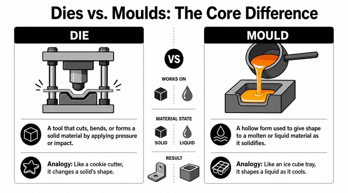
A mould works differently. It gives shape to a liquid, molten, or highly pliable material inside a cavity, then holds that shape while the material cools, cures, or solidifies. Injection moulding, blow moulding, and casting all sit in that family.
That's why the simple analogies are useful. A die is closer to a high-precision cookie cutter or forming tool. A mould is closer to an ice cube tray, except with far tighter control over temperature, venting, finish, and release.
Why the distinction matters on the factory floor
This isn't just vocabulary. The distinction affects what can go wrong.
With dies, you often focus on punch-to-die relationships, edge condition, material springback, forming sequence, and wear at contact points. With moulds, you spend more time managing fill behavior, cooling, venting, part shrinkage, parting lines, and ejection.
Die casting shows how technically demanding mould-like tooling can become. In that process, molten metal is injected into a die under 10 to 175 MPa of pressure, can achieve dimensional accuracy of about 0.1 mm for the first 2.5 cm plus 0.02 mm per additional centimeter, and can produce surface finishes around Ra 1–2.5 μm. Since 2018, shot sizes up to 80 kg have become possible, which helps explain why these tools remain central to high-volume industrial production, as summarized in this die casting reference.
A short visual walkthrough helps if you're explaining this to a mixed team of operations, quality, and purchasing:
The practical takeaway is simple. If your process shapes a solid by force, you're usually thinking in terms of dies. If your process fills a cavity with a liquid or molten material that then solidifies, you're usually thinking in terms of moulds. The design logic, maintenance profile, and automation concerns differ from there.
Exploring the Arsenal of Die and Mould Types
Manufacturers don't buy “a tool.” They choose from a menu of tooling architectures, and each architecture carries different assumptions about volume, complexity, maintenance, and line integration.
That scale is easy to underestimate. The global die and mould market was estimated at USD 43.5142 billion in 2024, with North America accounting for over 40% of revenue, and the market is projected to grow at a 4.7% CAGR through 2031, according to Cognitive Market Research's die and mould market report. Tooling is not a side category in manufacturing. It's one of the foundations.
Common die types and where they fit
Stamping dies are the first category many people think of. Progressive dies support repeatable, high-output production where multiple operations happen in sequence as material advances through the tool. Compound dies suit cases where multiple cutting actions happen in one stroke. Both can be excellent choices, but they lock in different assumptions about part flow, strip layout, and maintenance access.
Forming dies handle bending, drawing, and reshaping operations where material control matters as much as final geometry. They're often where teams discover that a part is technically manufacturable, but not reliably manufacturable at speed.
Extrusion dies shape material as it flows through an opening. These tools can look simple compared with some molding tools, but profile accuracy, wear resistance, and flow behavior still drive output quality.
Common mould types and what they change
Two-plate injection moulds are common because they're straightforward and reliable for many parts. Three-plate moulds add flexibility in gating strategy. Hot runner moulds can support cleaner material flow and different production economics, but they also raise the bar for thermal control and maintenance discipline.
Blow moulds fit hollow parts. Compression moulds suit applications where material is placed into the cavity and formed under heat and pressure. In each case, the right choice depends less on textbook definitions and more on your real production environment.
A tool that looks elegant in CAD can still be a poor production tool if maintenance access, vent cleaning, or part removal weren't thought through.
How toolmaking methods affect business outcomes
The way a tool is made has direct consequences for cost and lead time. CNC machining handles much of the base geometry. EDM becomes critical when details, corners, or hard materials make conventional machining inefficient or impossible. Heat treatment changes durability, distortion risk, and finishing effort.
That's why tool complexity compounds. Every added shutoff, insert, lifter, or difficult internal feature doesn't just add machining time. It changes fitting, inspection, repair strategy, and commissioning effort too. Shops that rely on wire cut EDM machines for precision tooling work understand this well, because the manufacturing method often determines whether a design remains practical to build and maintain.
Strategic Selection Criteria for Production-Ready Tooling
The cheapest quote rarely wins over the life of the program. It only wins on the day purchasing compares spreadsheets. After launch, production pays the actual bill.
Material choice is a maintenance decision
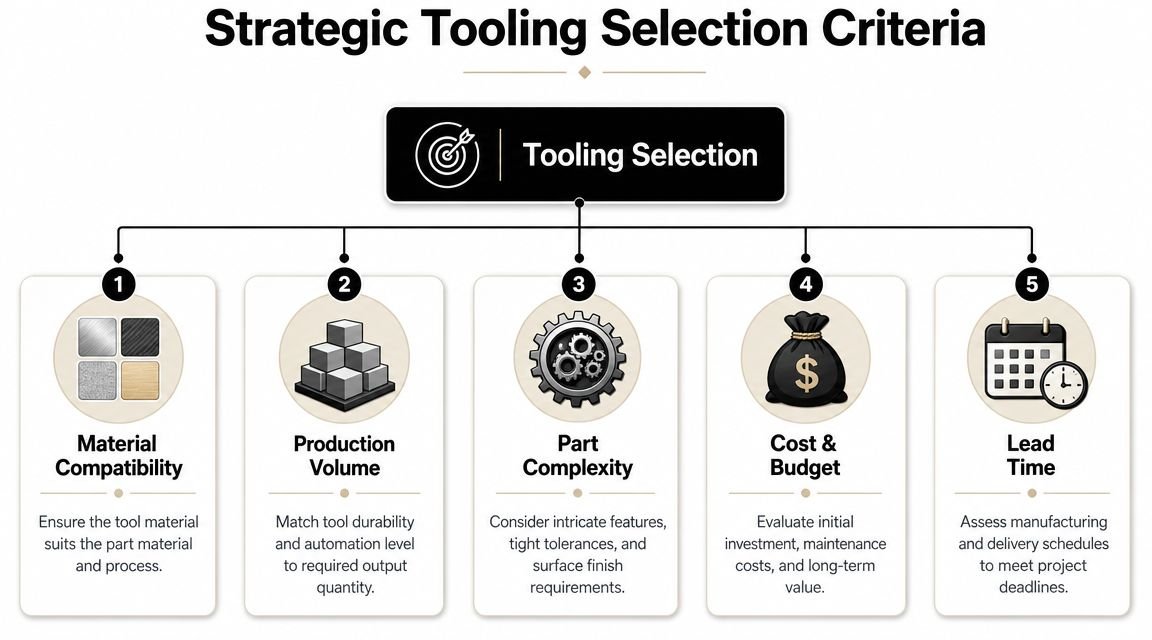
Tool material selection gets framed as an engineering detail, but it's really a maintenance and uptime decision. Harder steels, coatings, and better thermal stability usually cost more up front, yet they often make sense when abrasive materials, aggressive production schedules, or stricter part requirements are involved.
If the part material is demanding, a bargain tool usually becomes a service project. Edges wear faster. Surfaces degrade sooner. Shutoffs lose integrity. Then the line starts compensating with manual adjustments and more frequent stops.
Process intent matters. A prototype tool, a bridge tool, and a production tool should not be specified the same way. Teams get into trouble when they buy a short-life concept and expect long-life behavior.
Tolerance and finish should match functional risk
Toolmakers can hold impressive tolerances and finishes, but every tightening of the specification carries a price. More difficult machining, more grinding, more polishing, more inspection, and tighter assembly all show up in lead time and cost.
A published die-casting die specification illustrates what “tight” really means. It calls for general forming-dimension tolerances at IT9, with special dimensions tightened to IT6–T8 when required, and forming surfaces of inserts, cores, and gating-system surfaces at Ra 0.1–0.2 μm, while mating surfaces for guide posts, guide sleeves, push rods, and diagonal pins are typically held to Ra ≤ 0.8 μm, as described in this die-casting die specification reference.
Those numbers matter because finish and alignment affect flash, leakage, friction, and release behavior. But teams still need judgment. Not every feature deserves premium precision. Tighten what affects function, sealing, alignment, cosmetics, or validation risk. Don't overspecify invisible geometry just because it feels safer.
A useful review table looks like this:
| Tooling question | If you under-specify | If you over-specify |
|---|---|---|
| Critical dimensions | Part variation, assembly risk | Longer lead time, higher cost |
| Surface finish | Drag, release issues, cosmetic defects | Extra polishing without business return |
| Mating features | Misalignment, wear, leakage | More fitting effort than needed |
Volume determines the right class of tool
Production volume should drive tool class early, not after the first maintenance problem. For injection molds, SPI classifications make that decision more concrete. A Class 101 mold is intended for more than 1,000,000 cycles, while a Class 104 mold is limited to under 100,000 cycles and uses softer, less expensive materials, according to UPMOLD's summary of SPI mold classifications.
That's not just a durability label. It changes steel selection, cooling design, ejection approach, and how confidently you can automate the cycle.
Selection check: If annual demand, unattended runtime, and maintenance windows don't align with the mold class, the apparent savings disappear fast.
Teams that improve throughput consistently usually don't separate tooling from fixtures, handling, and operator interaction. They design those decisions together, which is why many manufacturers treat tooling and fixtures as a combined efficiency problem rather than two unrelated purchases.
Designing Dies and Moulds for Automation and GMP
Automation exposes weak tooling faster than manual production does. A human operator can wiggle a sticky part free, notice drag marks, or compensate for a fussy handoff. A robot usually can't. It repeats the programmed motion, and if the part doesn't release cleanly, the fault becomes a stoppage.
Draft, ejection, and robot stability
Draft angle is one of the clearest examples of a small design detail creating a major operational difference. General guidance often starts at 0.5° to 2° for simpler vertical faces, but deep pockets or textured surfaces may need 3° to 6° or more to avoid sticking and ejection trouble, as outlined in this draft-angle design discussion.
That matters more in automated cells than many teams expect. A part that releases inconsistently doesn't just create a cosmetic issue. It changes robot timing, vacuum pickup reliability, sensor confidence, downstream placement, and scrap handling.
The hard trade-off is that product teams often want near-zero draft to protect geometry or appearance. Manufacturing then inherits scraping, drag marks, longer release behavior, and heavier tool maintenance. Sometimes the right answer is more draft. Sometimes it's a slide, lifter, or design revision. What usually doesn't work is pretending the ejection problem will “sort itself out” at launch.
In automated production, draft is not just a design-for-manufacture issue. It's a design-for-repeatability issue.
Tooling choices that support GMP discipline
In regulated environments, especially medical device production, tooling has to support more than throughput. It has to support cleaning, repeatability, traceability, and controlled intervention.
That usually means avoiding unnecessary traps where residue, fines, or process debris can accumulate. It means choosing materials and finishes that support cleaning and inspection. It also means designing inserts, contact surfaces, and changeover points so technicians can service the tool without introducing confusion about reassembly or status.
For teams operating under good manufacturing practice expectations, the tooling strategy should align with the broader requirements for documentation, controlled processes, and contamination awareness described in this overview of GMP in manufacturing. A technically capable tool that is awkward to clean, difficult to verify, or inconsistent after maintenance creates compliance risk, not just production risk.
Design for the whole cell, not the cavity alone
Good automation-ready tooling includes the interfaces around the part, not just the cavity that forms it. That can include clear pickup access for end-of-arm tooling, stable presentation after ejection, sensor-friendly part orientation, and room for verification devices where they're needed.
A practical design review should ask:
- How does the part exit the tool: Is ejection force stable enough for unattended cycles, and does the part land or present in a repeatable way?
- Where will automation contact the part: Can a gripper or vacuum system engage it without touching a cosmetic or critical feature?
- What happens during faults: Can the cell recover safely from a short shot, stuck part, or incomplete ejection without damaging the tool?
- How is the tool serviced: Can technicians clean and inspect wear points without disturbing validated settings more than necessary?
In semi-automated lines, these details often matter even more because people and automation share the same process. The best die and moulds reduce the amount of human correction the system needs.
Your Action Plan for Tooling Procurement and Lifecycle Management
Most tooling problems start before the tool is cut. They start in the request, when the buyer asks for a part-forming device instead of a production-ready asset.
Start with a real URS
A strong user requirement specification should describe more than part geometry. It should define expected volume, part material, cosmetic standards, validation needs, maintenance constraints, automation interfaces, changeover expectations, and what counts as an acceptable cycle in production.
If your URS doesn't mention ejection reliability, cleaning access, spare components, or acceptance criteria, the supplier will make assumptions for you. Those assumptions may be reasonable. They may also be expensive.
Qualify the tool with production in mind
Vendor review should focus on capability, but also on fit. Ask how the supplier handles design reviews, tolerance stack-up, wear surfaces, serviceability, and production trials. Ask who owns debugging during runoff. Ask what documentation arrives with the tool.
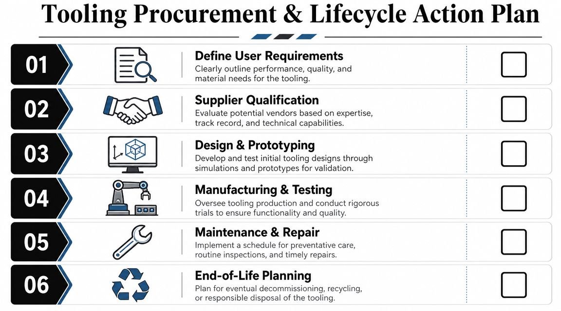
Factory Acceptance Testing and Site Acceptance Testing shouldn't be treated as formalities. They're where you confirm that the tool behaves inside a process, not just on a bench. For production tooling, acceptance should include part quality, repeatability, fault response, and interaction with the actual line environment.
A practical procurement checklist includes:
- Define operating reality: State real output expectations, staffing assumptions, and whether the cell is manual, semi-automatic, or fully automated.
- Specify critical-to-quality features: Separate must-hold dimensions and finishes from noncritical geometry.
- Require maintenance clarity: Identify wear items, spare insert strategy, and expected service access.
- Test under realistic conditions: Run acceptance with production-representative materials, operators, and automation states.
Manage the tool after launch
Lifecycle management is where tooling value is protected or lost. Preventive inspection, repair records, spare part planning, and revision control all matter. In regulated plants, they matter even more because undocumented adjustments can turn a maintenance event into a quality event.
The best-performing manufacturers don't stop at tool delivery. They manage the die or mould as a controlled asset with a history, a service plan, and clear ownership across engineering, maintenance, quality, and operations.
If you're evaluating die and moulds as part of a broader effort to improve throughput, reduce manual intervention, or build a more GMP-aware production process, System Engineering & Automation can help. SEA develops practical manufacturing solutions that connect tooling, fixtures, controls, and the right level of automation to your actual production goals, so the result works on the floor, not just in a design review.