A production line is running, operators are loading parts on time, and the HMI looks normal. Then the MES stops receiving the right status tags from the PLC. One station waits for a handshake that never comes. Another keeps cycling because a completion bit mapped to the wrong state. Maintenance checks wiring. Controls checks logic. IT checks the server. An hour later, everyone realizes the actual problem started much earlier. The hardware and software were never aligned tightly enough in design.
That's the reality behind many integration failures in manufacturing. The parts can all be good on their own and still fail together. In plants upgrading manual or semi-automatic processes, budgets often get chewed up and schedules slip. The underlying issue isn't usually one bad component. It's the seam between PLC code, device firmware, electrical design, data structures, operator workflow, and validation expectations.
That seam matters more than many teams admit. Hardware-software integration issues cost the global economy approximately $2.4 trillion annually, driven by misalignment between physical capabilities and software requirements that create bottlenecks and system instability, according to Compound's analysis of hardware-software integration costs. For manufacturers trying to optimize production and service performance, that's not an abstract engineering statistic. It's line downtime, rework, missed output, and expensive late fixes.
Table of Contents
- Introduction to Hardware and Software Integration
- Gathering Requirements And Defining Project Scope
- Designing Architecture Components for Automation
- Establishing Communications And Control Interlocks
- Developing Software Stack And Integrating MES SCADA
- Testing Validation And GMP Compliance
- Conclusion And Maintenance With ROI Insights
Introduction to Hardware and Software Integration
Hardware and software integration in manufacturing is the disciplined work of making machines, controls, sensors, firmware, HMIs, SCADA, MES, and plant procedures behave like one system instead of a stack of separate purchases. That sounds obvious. In practice, many factories still treat the machine build, controls programming, and software integration as handoffs between teams that only partially overlap.
The trouble usually shows up at commissioning. A servo drive is sized correctly, but the motion profile assumed by the application layer doesn't match the actual mechanical response. A barcode scanner reads fine in a bench test, but the string format doesn't match what the MES expects. A vision system detects defects reliably, but the reject confirmation never closes the loop with the PLC and the lot record remains incomplete.
Practical rule: If the first serious conversation between controls, firmware, and operations happens after hardware is built, the project is already carrying avoidable risk.
In plants that need cost-effective automation to optimize production and services, the winning approach is concurrent co-design. That means electrical, mechanical, controls, and software teams define timing, interfaces, failure states, traceability, and operator actions together. They don't wait for one discipline to “finish” before another starts adapting around it.
A sound integration effort usually has a few visible traits:
- Shared requirements early: Teams agree on signals, states, recipes, alarms, and reporting before code and panel layouts are frozen.
- Real interface ownership: Someone owns each boundary, such as PLC-to-SCADA tags, scanner-to-controller messages, or vision results to reject logic.
- Testing under plant conditions: Validation happens with realistic loads, temperatures, cycle times, and operator interactions, not only at a desk.
Plants that get this right usually don't talk about integration as a separate project headache. They experience it as smoother startup, fewer surprises during commissioning, and cleaner handoff into production.
Gathering Requirements And Defining Project Scope
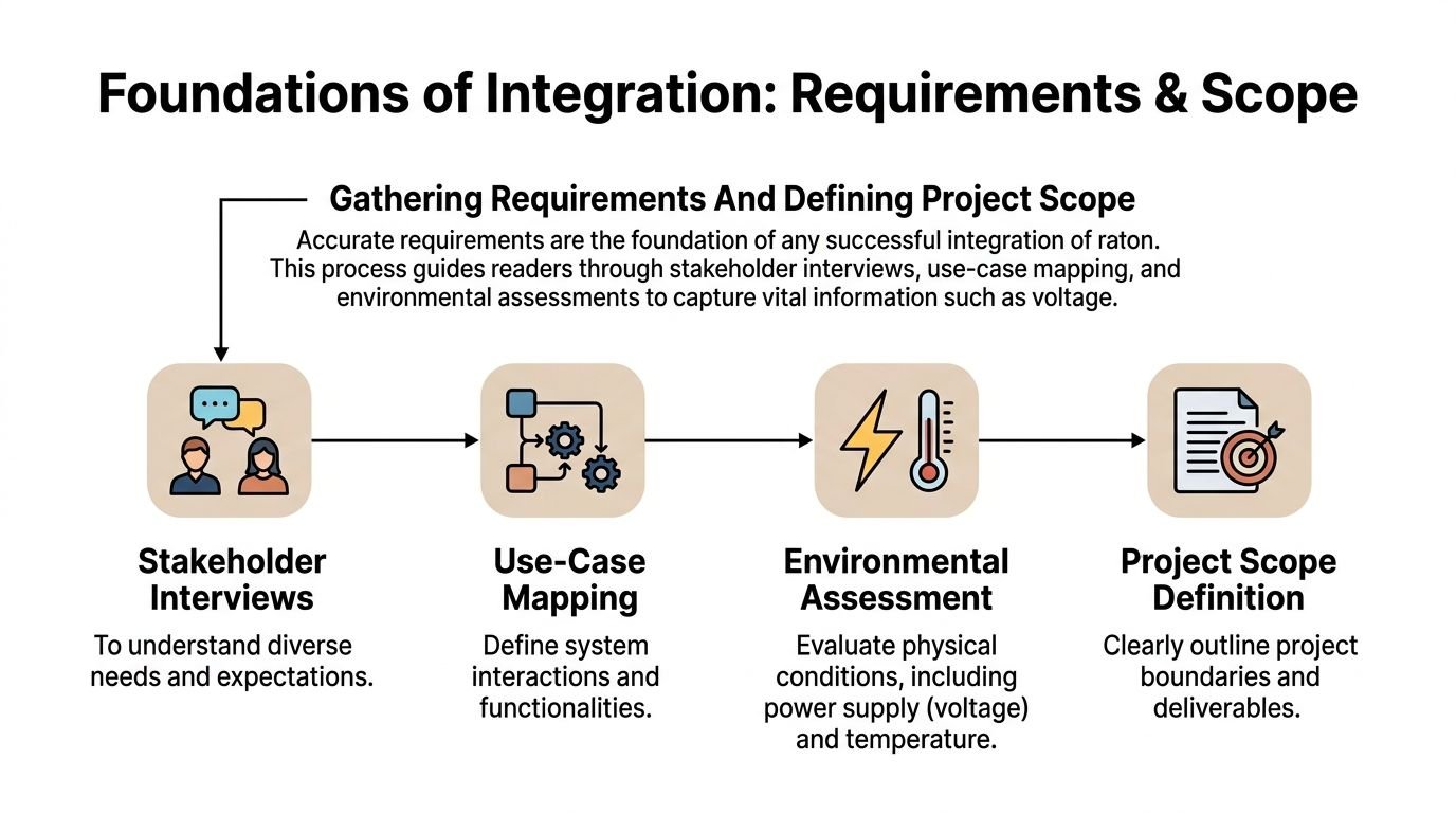
Bad integration often starts with vague requirements. Someone says the line needs “traceability,” but nobody defines what data must be stored, where it lives, who reviews it, and what happens if a device drops a transaction. Someone specifies “real-time alarms,” but no one agrees on acceptable latency or escalation behavior. Those gaps become expensive once panels are wired and code is halfway written.
A disciplined hardware and software integration process starts with requirement capture, not hardware selection. A rigorous 8-step methodology mandates defining requirements and compatibility, including voltage levels, data formats, and protocols, before moving into development, end-to-end testing, and version-controlled maintenance, as outlined by Hyetech's hardware and software integration best practices.
Start with the production reality
The best requirement reviews happen on the floor, not only in a conference room. Walk the process. Watch how operators load, inspect, clear faults, and record exceptions. Ask quality what must be retained in the batch or device record. Ask maintenance what usually fails first and what they need visible on the HMI to troubleshoot without opening a cabinet.
Capture these items in plain language before converting them into technical documents:
- Electrical constraints: Voltage levels, I/O type, grounding concerns, and field device compatibility.
- Data behavior: Tag names, message structure, update rates, historian needs, and required records for traceability.
- Environmental exposure: Washdown, vibration, temperature swings, dust, compressed air quality, and cabinet limitations.
- Regulated process needs: Change control expectations, audit trail requirements, login roles, and evidence needed for validation.
Teams also need to define what the machine will not do. Scope creep thrives when “future-ready” gets used as a substitute for disciplined decision-making. Leave room for expansion, yes. Don't load phase one with every hypothetical request.
The cleanest projects I've seen had a hard boundary between required production functions and optional enhancements. That prevented late additions from breaking tested logic.
Build the documents that prevent arguments later
In industrial automation, scope and interface documents are where integration either becomes manageable or chaotic. A formal 9-step engineering process requires scope definition, requirements capture, and interface specification through an Interface Control Document, or ICD, before FAT and SAT, according to Industrial Automation Authority's system integration process guidance.
An ICD should define at minimum:
| Item | What to define |
|---|---|
| Signal ownership | Which device originates the value and which device consumes it |
| Data type | Boolean, integer, float, string, structured record |
| Update behavior | Event-driven, polled, cyclic, buffered |
| Error handling | Timeout response, retry logic, fallback state |
| State logic | Ready, busy, complete, fault, hold, reset |
That document sounds tedious until the first integration test. Then it becomes the fastest way to settle disagreements.
A practical scoping package usually includes a use-case list, I/O summary, compatibility matrix, alarm philosophy, and a draft sequence narrative. In regulated manufacturing, add traceability points and change control expectations at the same time. If those are deferred, software and documentation drift apart quickly.
Designing Architecture Components for Automation
Architecture decisions aren't made in a vacuum. They're shaped by cycle time, product mix, maintenance skill level, plant standards, available cabinet space, environmental conditions, and how much change the line will face over its life. The wrong architecture can still run. It just becomes hard to troubleshoot, expensive to extend, or brittle under process changes.
The market pressure behind these choices is increasing. The global system integration market is projected to reach $872.23 billion by 2032 with a 10.5% CAGR, and joint hardware-software partnerships can cut development cycles by up to 30% while accelerating time to market by 25%, according to Zco's review of hardware-software integration trends.
Early in architecture planning, it helps to visualize the control hierarchy clearly.
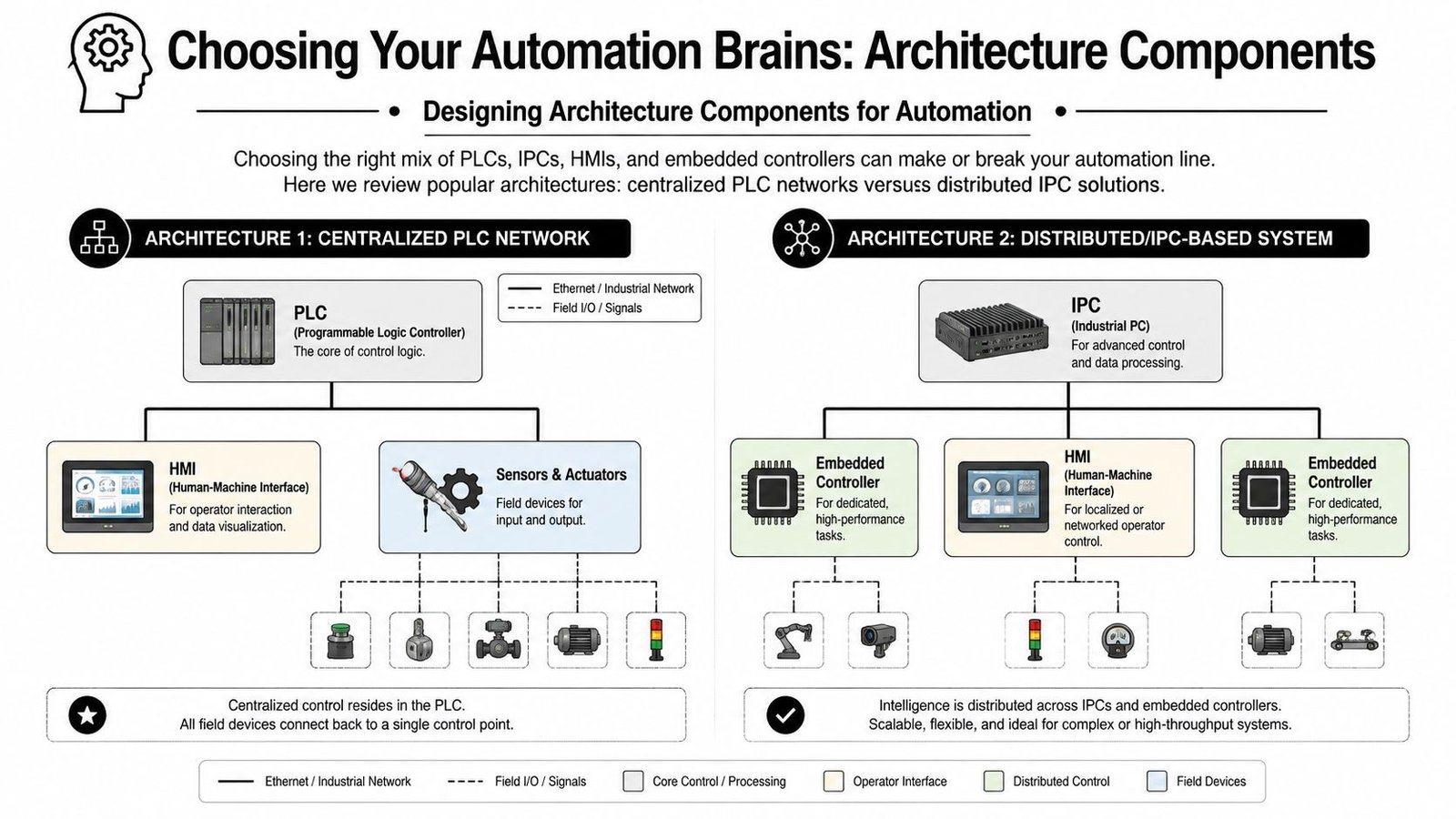
When a centralized PLC architecture fits best
A centralized PLC network is still the right answer for many semi-automatic and repeatable production tasks. If the process is deterministic, the I/O count is manageable, and operators need a straightforward HMI with stable recipe handling, a PLC-centered design often gives the best balance of reliability and maintainability.
This approach tends to work well when you have:
- Discrete machine logic: Indexing, presence checks, part clamping, pneumatic actuation, and standard alarm handling.
- Plant maintenance ownership: Electricians and controls technicians already support PLC platforms comfortably.
- Tight uptime needs: Standardized hardware makes spares and troubleshooting more predictable.
For manufacturers evaluating machine concepts, automation systems design services are most effective when architecture selection is tied to actual production goals, not brand preference or habits from a previous line.
A centralized PLC design is often easier to validate and support. The trade-off is flexibility. Once advanced vision processing, heavy data handling, or custom analytics enter the picture, the architecture can start bending around limitations.
A short video can help frame these architecture choices in a practical way:
When IPC and distributed control earn their keep
Distributed or IPC-based systems make sense when the machine has more moving parts in the software layer than in the mechanical one. Vision-guided assembly, data-heavy inspection, recipe variation, and advanced coordination across multiple stations usually justify an industrial PC or embedded controller in the architecture.
The upside is clear. You get stronger compute options, richer software frameworks, and easier handling of complex libraries or SDKs. The downside is just as real. Maintenance discipline must improve. Version control matters more. Patch management, backups, and cyber hygiene can't be casual.
A simple selection view
| Architecture | Best fit | Strength | Main caution |
|---|---|---|---|
| Centralized PLC | Repeatable machine cycles | Reliable, maintainable control | Limited flexibility for advanced compute tasks |
| PLC plus edge devices | Mixed automation cells | Balanced expansion path | More interfaces to define and test |
| IPC or distributed control | Vision-heavy, data-rich lines | High capability and scalability | Higher software management burden |
The right architecture is rarely the most complex one. It's the one your plant can run confidently after the integrator leaves.
Establishing Communications And Control Interlocks
Communication design and interlock design should never be treated as separate topics. The protocol determines how fast data moves, how errors are reported, and how state transitions get confirmed. Interlocks determine what the machine is allowed to do when those messages arrive late, arrive malformed, or don't arrive at all.
That's why hardware and software integration problems often surface as “random faults.” They aren't random. They're usually unhandled edge cases at system boundaries.
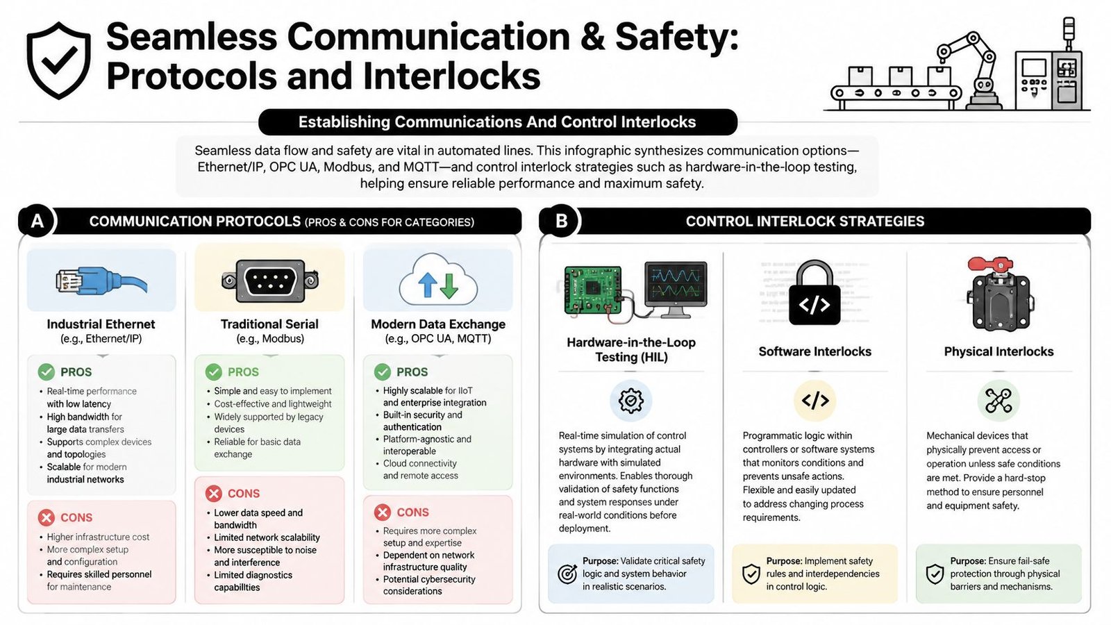
Protocol choice changes control behavior
Ethernet/IP, Modbus, OPC UA, and MQTT can all belong in an industrial system, but they solve different problems.
- Ethernet/IP: Strong fit for real-time industrial control, especially where PLCs, drives, and remote I/O must exchange deterministic data.
- Modbus: Useful for simple device integration and legacy equipment, especially when supportability matters more than elegance.
- OPC UA: Strong option for structured data exchange between machines and higher-level software, especially when context and interoperability matter.
- MQTT: Useful when event-based data publishing and broader connectivity are needed, but it shouldn't be treated as a drop-in replacement for hard control logic.
Plants working on connected equipment and visibility layers often benefit from tighter telemetry and process controls planning because data transport and control intent need to be defined together.
The mistake is choosing a protocol because it's modern or familiar. The right question is simpler: what data must move, how fast, under what failure conditions, and who depends on it?
A good handshake does more than pass data. It confirms readiness, execution, and fault state in a way every connected device interprets the same way.
Interlocks need both logic and proof
Interlocks start with safety and process protection. They only become trustworthy after testing proves them under realistic conditions. Teams improve integration outcomes when they implement hardware-in-the-loop testing, integrate hardware tests into CI/CD pipelines, and automate at least 70% of regression tests, yielding sub-1% annual downtime, according to Zigpoll's guidance on seamless hardware-software integration strategies.
Good interlock practice usually includes a mix of layers:
- Physical interlocks: Guard switches, e-stops, contactors, keyed access, and hardwired safety functions.
- Software interlocks: Recipe validation, motion inhibit states, process sequencing, and fault latching.
- Test interlocks: Simulated sensor states, timeout testing, forced communication loss, and recovery scenarios.
For troubleshooting, measure more than “works” or “doesn't work.” Check latency, throughput, dropped transactions, and signal integrity. In many installations, the root cause is a timing mismatch or retry behavior that no one tested under actual load.
Developing Software Stack And Integrating MES SCADA
The software stack in an automated line should be built from the bottom up, but designed with the top-level business need in mind. That means firmware, drivers, PLC logic, HMI behavior, SCADA screens, alarm routing, and MES transactions all need a shared model of the process. If each layer invents its own state logic, the system becomes fragile fast.
Build from firmware upward
The lower layers deserve more design effort than they usually get. Drivers and firmware should expose clean, predictable interfaces to the control layer. If a vision sensor or torque tool comes with an SDK, wrap it in a modular way so the machine logic doesn't become tangled with vendor-specific calls.
A practical sequence looks like this:
- Define device behavior first. What does the scanner, camera, scale, or embedded controller report when it is ready, busy, faulted, or offline?
- Normalize the interface. Convert vendor-specific responses into machine states the PLC or supervisory layer can handle consistently.
- Separate timing-sensitive logic. Keep high-speed acquisition, buffering, and device retries near the hardware-facing layer.
- Promote only useful data upward. Don't flood SCADA or MES with every low-level value. Send what operations, quality, and maintenance need.
Many integrations become messy. Engineers often expose raw device details to every software layer, then spend weeks patching around inconsistency. Cleaner abstraction early prevents that.
Keep the PLC focused on machine control, the firmware focused on device behavior, and the MES focused on production truth. Mixing those responsibilities causes long commissioning nights.
Connect plant-floor events to business systems carefully
SCADA and MES integration should reflect production events, not just tag values. “Cycle complete” on a PLC doesn't automatically mean “good unit produced” in the MES. You may still need confirmation from inspection, operator action, or a downstream station.
For regulated or traceability-heavy environments, the database and application layer should capture relationships, not isolated records. Typical examples include:
- Unit genealogy: Which serial number used which subcomponents, tooling, recipe, and inspection result
- Process context: Operator ID, station ID, timestamp, lot reference, and exception codes
- Reviewable events: Alarm acknowledgments, bypasses, rejected units, and retest outcomes
API-first patterns can help keep this stack maintainable, especially when machine software needs to evolve while plant reporting stays stable. The key trade-off is complexity. More modularity gives cleaner updates, but only if naming, versioning, and ownership stay disciplined.
The strongest MES and SCADA integrations don't just display data. They preserve the truth of what happened on the line in a format operations and quality teams can trust.
Testing Validation And GMP Compliance
Many teams still assume that if a machine passes FAT and later clears SAT, the integration is “done.” That assumption fails quickly in regulated manufacturing. FAT and SAT are useful. They are not, by themselves, a GMP validation strategy.
A production asset for medical devices or similarly controlled products has to prove more than basic functionality. It has to show traceability, controlled change, documented risk handling, and repeatable performance under defined conditions.
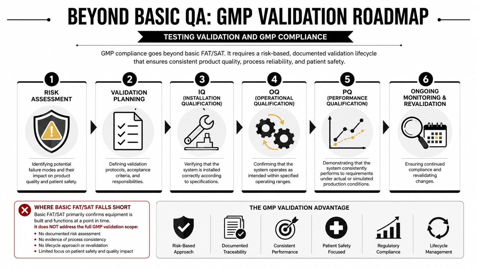
Basic FAT and SAT are not enough
FAT checks whether the machine was built and functions as intended before shipment. SAT checks whether it runs properly after installation. Both matter. Neither fully answers GMP questions such as traceability of software changes, evidence of intended use, or how risk controls were verified across revisions.
In regulated environments, validation work usually needs a fuller chain:
- Risk assessment: Identify failure modes that can affect product quality, process control, or operator action.
- Validation planning: Define what will be tested, who approves it, and what evidence will be retained.
- IQ: Verify the installed system matches the approved design and documented configuration.
- OQ: Challenge operating ranges, alarms, interlocks, and intended functional behavior.
- PQ: Show the integrated system performs consistently in production-representative conditions.
- Ongoing change control: Revalidate the affected scope when hardware, software, or recipes change.
For teams that need a practical baseline on formal acceptance work, FAT testing guidance is useful as part of the broader validation picture, but it should never be mistaken for the entire compliance framework.
Why modular architecture matters in regulated lines
A major gap in common integration advice is GMP-specific modular architecture. Addressing that gap reduces validation cycles by ensuring independent testing and traceability in regulated medical device environments, as described in TIWeb's review of hardware-software integration challenges in automation.
That matters because modularity isn't just a software elegance issue in a GMP setting. It changes how much of the system must be retested after a revision. If a vision module, label verification function, or data collection service can be isolated cleanly, teams can limit the validation impact of changes. If everything is tangled together, one update can trigger broad retesting and documentation churn.
A practical GMP-aware validation package should include:
| Validation element | Why it matters |
|---|---|
| Traceability matrix | Links requirements to code, tests, and approval evidence |
| Controlled revision history | Shows what changed, when, and why |
| Defined user roles | Supports security and operational accountability |
| Exception handling records | Preserves evidence of faults, interventions, and deviations |
In regulated plants, modular design saves effort twice. It simplifies the original build, and it limits the blast radius when changes come later.
The strongest teams treat validation as part of design, not a paperwork exercise after controls are complete.
Conclusion And Maintenance With ROI Insights
A well-integrated machine doesn't stay well-integrated by accident. Firmware versions change. Replacement devices arrive with different revisions. Network loads shift. Operators develop workarounds. Production introduces a new SKU that stresses timing, recipes, or inspection criteria in a way the original build didn't. Maintenance is where integration quality is either preserved or degrades over time.
Maintenance protects the original investment
The most useful maintenance plans are boring in the best sense. They rely on routine version control, documented backups, scheduled firmware review, monitored alarms, spare-part discipline, and remote diagnostic access that's governed properly. Plants that skip those basics often end up blaming hardware when the underlying issue is uncontrolled software drift.
A practical lifecycle checklist includes:
- Version-controlled releases: Keep PLC, HMI, IPC, firmware, and configuration files tied to approved revisions.
- Change review before deployment: Check interface impacts before loading new code or swapping field devices.
- Trend-based diagnostics: Watch recurring faults, rising cycle times, communication retries, and data gaps.
- Spare strategy: Stock the devices whose failure would stop the line, especially if replacement lead times are uncertain.
What ROI looks like on the plant floor
The business case for integration gets clearer after startup. Factory automation integration that connects hardware such as PLCs, CNCs, and sensors with software platforms such as MES and ERP yields 10–20% production output improvements and enables 10–15% additional capacity without new equipment purchases, according to Controlink Systems' analysis of integration support in factory automation upgrades.
That kind of return usually comes from a combination of effects, not one dramatic fix. Better sequencing reduces idle time. Cleaner data reduces manual intervention. Interlocks prevent avoidable scrap. Operators spend less time recovering from nuisance faults. Quality gets clearer records. Maintenance diagnoses problems faster.
Plants also benefit when integrated systems generate useful production data instead of disconnected signals. Manufacturers that connect operational and information technology typically use categories such as operational performance, machine health, quality control, safety interlocks, and energy consumption, as outlined in Plant Engineering's discussion of making plant data work harder.
The strongest ROI comes from discipline established before startup and sustained after handoff. Integration isn't a commissioning task. It's an operating strategy.
If you're planning a new line, upgrading a semi-automatic process, or trying to bring order to a machine that never fully integrated, System Engineering & Automation helps manufacturers build practical, GMP-aware automation systems that improve quality, efficiency, and service performance without overbuilding the solution.