A line goes live for commissioning on Monday. By Tuesday afternoon, the new robotic arm can cycle, the legacy conveyor can run, and the vision station can inspect. But the systems still won't work together. One vendor says the PLC tags were never finalized. Another says the sensor timing window was assumed, not specified. Your maintenance team is standing by, production is asking when the line will release, and quality wants to know what changed from the validated concept.
That situation is common in semi-automated manufacturing. It shows up when a cartoner needs to exchange status with a checkweigher, when a smart fixture has to report pass/fail to a MES layer, or when a custom test station has to handshake cleanly with an upstream operator station. The problem usually isn't that the machines are bad. It's that the interface between them was never documented with enough discipline.
That is where interface control documentation earns its keep. Done well, it acts as the technical agreement that keeps mechanical, electrical, controls, software, quality, and vendor teams aligned before steel is cut and before code is released to the floor. For manufacturers looking to optimize production and services, that discipline isn't paperwork for its own sake. It's one of the most practical ways to reduce avoidable delays, protect quality, and keep an automation project from stalling at the finish line.
Table of Contents
- Why Automation Projects Fail at the Finish Line
- Defining the ICD for Modern Manufacturing
- Core Components of a Bulletproof ICD
- The Creation and Review Workflow
- Managing Change and Ensuring GMP Compliance
- Common Pitfalls and Dynamic Interface Control
Why Automation Projects Fail at the Finish Line
A common failure point isn't machine build quality. It's integration.
A plant replaces a manual transfer with a robotic pick-and-place cell. The robot supplier delivers a clean installation. The conveyor OEM confirms the legacy line is operational. During commissioning, the robot waits for a ready signal that never arrives, the conveyor expects a permissive that uses a different tag state, and the reject confirmation from the vision system isn't mapped the way either team assumed. Everyone has hardware. Nobody has agreement.
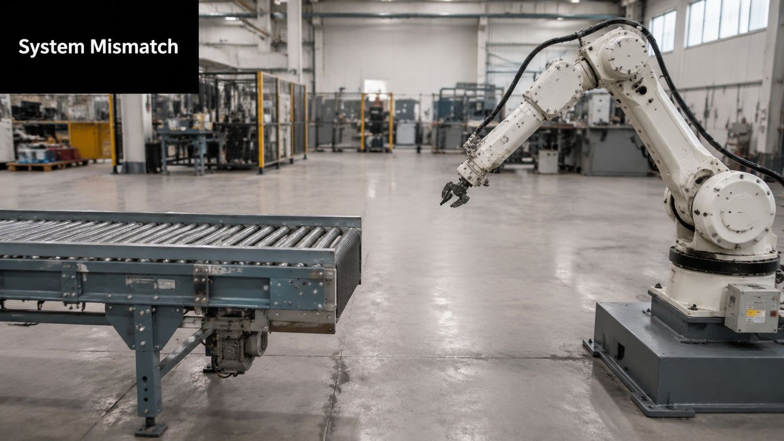
That kind of breakdown creates a familiar chain reaction. Controls engineers start tracing signals on the floor. Mechanical teams check bracket positions and cable routing because they don't trust the as-built assumptions anymore. Production loses schedule confidence, and management starts paying for extra troubleshooting that should have been eliminated during design.
The problem is usually between systems
Most project teams document their own equipment well enough. The robot manual exists. The conveyor drawings exist. The HMI screens exist. What often doesn't exist is a single controlled document that defines exactly how those systems connect and behave at the boundary.
That boundary matters more than many teams admit. Interface Control Documents are a foundational element of systems engineering, ensuring that separately developed parts of a system can reliably exchange signals or physical information. This controlled documentation is a mandatory artifact for integration, verification, and change control activities that prevent costly rework and system incompatibility during the 10-20 year lifespans typical of complex aerospace and medical device automation projects, as outlined in the Interface Control Document overview.
Practical rule: If two teams can each point to a different document and both claim they're right, you don't have interface control. You have a commissioning argument waiting to happen.
What an ICD changes on the plant floor
A solid ICD turns assumptions into explicit decisions. It defines what signal comes from where, what connector is used, what message format is expected, who owns each side of the boundary, and how changes get approved. It gives the plant manager something better than verbal alignment. It gives the project a technical contract.
In semi-automated manufacturing, that's a direct operational advantage. It supports faster troubleshooting, cleaner handoffs to maintenance, and fewer surprises when a line evolves. It also keeps third-party vendors from solving interface issues in isolation, which is one of the fastest ways to create hidden incompatibilities.
Defining the ICD for Modern Manufacturing
An Interface Control Document, or ICD, is the document that defines how two parts of a system connect and interact. In manufacturing, that can mean a physical mount between a fixture and a press, an electrical handoff between a PLC and a servo drive, or a data exchange between a test station and an enterprise system.
The easiest way to think about it is this. A functional specification says what the machine needs to do. An ICD says how one part of that machine, or one machine to another, will communicate and fit together.
What an ICD is, and what it isn't
An ICD is not a full system design package. It shouldn't try to explain every internal detail of each connected system. The document stays focused on the interface itself.
That boundary is important in formal guidance. The ECSS-E-ST-10-24C standard requires the ICD to define the complete design of interfaces by documenting form, fit, and function, and it calls for technical details such as input and output signals, message formats, data types, units, scales, limits, tolerances, transmission periodicity, communication protocols, connector characteristics, and change history, as described in the ECSS interface control standard annexAnnexB_Interface-Control-Document-(ICD).doc).
For a plant team, that means the ICD should answer questions like these:
- Mechanical connection: What mounting pattern, orientation, clearance, and mating features apply?
- Electrical interface: What voltage level, signal type, pinout, shielding, and grounding expectations apply?
- Data exchange: What message structure, timing, protocol, and error behavior apply?
- Operational boundary: What must be true before transfer, start, stop, reject, or reset can occur?
Why manufacturing teams need a narrower, sharper document
A weak document blends requirements, design rationale, software behavior, and operating instructions into one messy file. That makes review difficult and ownership unclear.
A better ICD acts like a technical handshake. It tells each side exactly what they must provide at the interface and nothing more. That clarity matters when you're integrating new equipment into an existing line, retrofitting smart tooling into a manual workstation, or connecting semi-automatic equipment to GMP-controlled processes.
When the interface is documented correctly, each team can design its own side with confidence. When it isn't, teams fill gaps with assumptions.
That is why disciplined interface control documentation belongs early in a project. If you're standardizing technical deliverables across automation work, strong technical documentation standards make ICDs easier to review, easier to maintain, and far more useful during commissioning.
Core Components of a Bulletproof ICD
A usable ICD doesn't win on length. It wins on precision.
The best ones are boring in the right way. They don't leave room for interpretation, and they don't assume the reader already knows what the writer meant. On a factory floor, that kind of precision is what prevents wiring changes during startup, last-minute PLC edits, and awkward workarounds that become permanent.
What the document must define
For manufacturing automation, these are the sections that matter most.
Interface identification
Name the two interfacing items clearly. Example: "Cell PLC to Servo Drive A" or "Vision Station Reject Output to Packaging Line PLC." Add document number, revision, owner, and status.Scope and boundary
Define where the interface starts and stops. If the ICD covers only the electrical and data boundary between a custom fixture and the main machine PLC, say that directly. Don't let teams assume it includes unrelated machine logic.Mechanical details
Include mounting coordinates, fastener requirements, allowable clearances, connector locations, access zones, and mating orientation. If alignment matters, show it in drawings. If tolerance stack-up matters, write it down.Electrical characteristics
Capture signal list, source and destination, normal states, fail-safe states, voltage levels, terminal references, pin assignments, and cable requirements. If a signal is pulse-based or edge-triggered, don't leave that implied.Data exchange definition
When systems communicate over software, the ICD must get specific. Message formats, data types, units, protocol, port use, update frequency, and fault handling all belong here. For data-exchange interfaces, the ICD must define message structure, protocols such as API or SFTP, specific ports, and estimated data size and frequency, according to the CMS interface control document template.Verification method
Every requirement should tie to a practical check. Inspection, bench test, I/O checkout, dry-cycle confirmation, FAT step, or SAT step. If you can't verify it, you haven't defined it well enough.Revision and change history
List what changed, when it changed, who approved it, and what other documents were affected.
A practical interface matrix example
One of the simplest ways to make an ICD usable is to include an interface matrix. It gives the controls team, electricians, and commissioning staff a fast reference that cuts through narrative text.
Example Interface Matrix: PLC to Servo Drive
| Signal Name | Source | Destination | Signal Type | Description |
|---|---|---|---|---|
| Servo Enable | Cell PLC | Servo Drive | Digital Output | Permits drive operation when safety and machine-ready conditions are met |
| Drive Ready | Servo Drive | Cell PLC | Digital Input | Confirms drive is powered and available for command |
| Fault Status | Servo Drive | Cell PLC | Digital Input | Indicates drive fault condition requiring alarm handling |
| Speed Reference | Cell PLC | Servo Drive | Analog or Network Data | Commands target operating speed |
| Actual Speed | Servo Drive | Cell PLC | Analog or Network Data | Returns measured drive speed for monitoring |
| Reset Fault | Cell PLC | Servo Drive | Digital Output | Sends operator-initiated fault reset command |
A table like this should never stand alone. Back it with wiring references, tag naming conventions, timing notes, and state definitions. "Ready" sounds obvious until one team means powered, another means homed, and a third means safe to cycle.
On real projects: Words like ready, done, faulted, and complete cause trouble unless the ICD defines the exact machine state behind them.
A bulletproof ICD also reflects the physical world. If a connector can be installed in the wrong orientation, document the keying. If a pneumatic handshake depends on line pressure stabilization, include the condition. If a servo motion profile relies on a scaling factor, define the units and allowed range. Those details feel small in design review. They become very large during commissioning.
The Creation and Review Workflow
Strong interface control documentation doesn't appear at the end of the job. It has to be built into the workflow while requirements, design, and procurement are still moving.
The process doesn't need to be bureaucratic. It does need ownership, review discipline, and a release path that people follow.
Who owns what
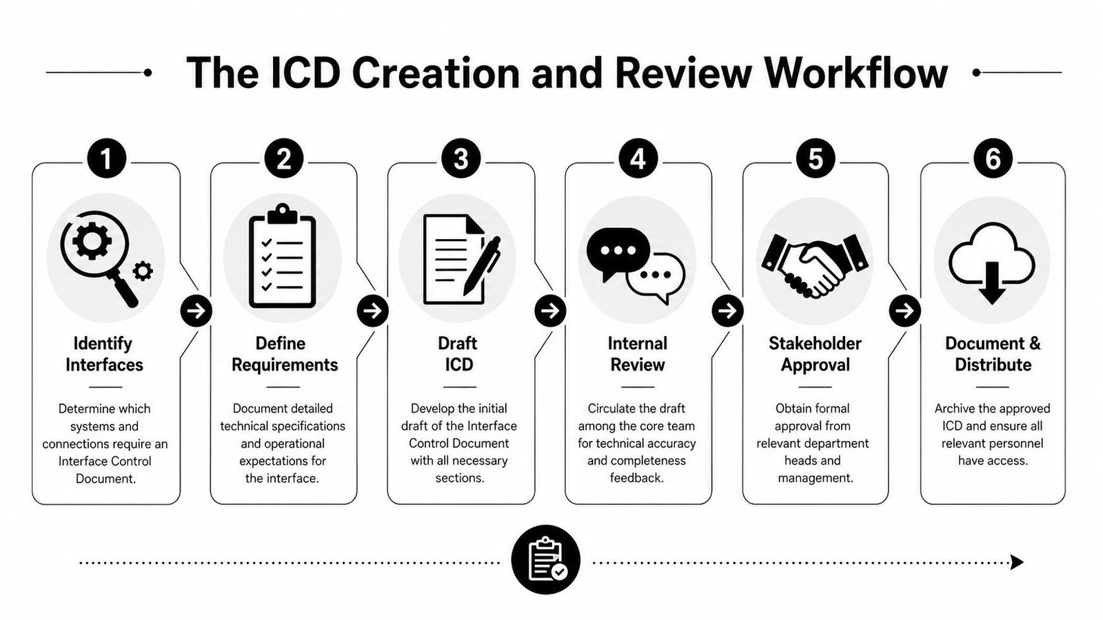
The first practical step is to identify interfaces at the system level. On a semi-automated line, that usually means power, mechanical connections, safety circuits, network communication, production data flow, operator handoff points, and material transfer boundaries.
After that, assign owners. One person has to be the custodian for the document, and each side of the interface needs a subject matter expert who can approve technical content. In a plant environment, that may mean controls engineering on one side and IT, tooling, validation, quality, or maintenance on the other.
A workable ownership model often looks like this:
Custodian
Maintains the document, revision history, and approval flow.Interface-side SMEs
Confirm the details for their own equipment, software, or process boundary.Quality or QA reviewer
Checks traceability, verification method, and document alignment for validated environments.Project lead or control board
Resolves conflicts and approves changes that affect cost, schedule, or scope.
How the workflow should move
A disciplined sequence has been well described in the INCOSE presentation on writing and managing interface requirements, including identifying interfaces at the highest system level, defining boundaries with an Interface Requirements Document, assigning a custodian and SMEs, establishing a control board, updating at milestones such as SRR, PDR, CDR, and TRR, and aligning ICDs with verification and validation activities.
On the plant floor, the practical version looks like this:
Identify the interfaces early
Don't wait until code review. If the project includes a vision station, a PLC, a robot, and an ERP or MES handoff, each boundary should be named before detailed design starts.Draft from the boundary inward
Start with what must cross the interface. Signals, states, connectors, messages, physical constraints. Don't begin with internal design details that the other side doesn't need.Review with the people who will feel the failure
Include controls, mechanical, quality, and the people who will run FAT and SAT. If a commissioning technician can't use the ICD, it's too abstract.Approve before build and before test
If the ICD changes after panels are wired or after software is validated, the review bar should go up.
A useful checkpoint is to align ICD review with factory acceptance tests. If a signal, message, or mechanical interface can't be tested cleanly at FAT, the document probably missed something.
A rushed FAT often exposes an ICD problem that was created months earlier.
Managing Change and Ensuring GMP Compliance
An ICD isn't a one-time deliverable. It's a living controlled record. That matters on every automation project, but it matters even more when the equipment supports a regulated manufacturing process.
In GMP-aware environments, undocumented interface changes create two problems at once. They increase technical risk, and they weaken the evidence trail that quality teams need when they review the validated state of a system.
Why version control matters on regulated equipment
A line rarely stays frozen after startup. A sensor gets relocated. An HMI field changes. A smart fixture starts sending an extra status bit. A PLC routine gets revised to handle a new reject condition. Each of those can alter the interface, even when the change looks minor.
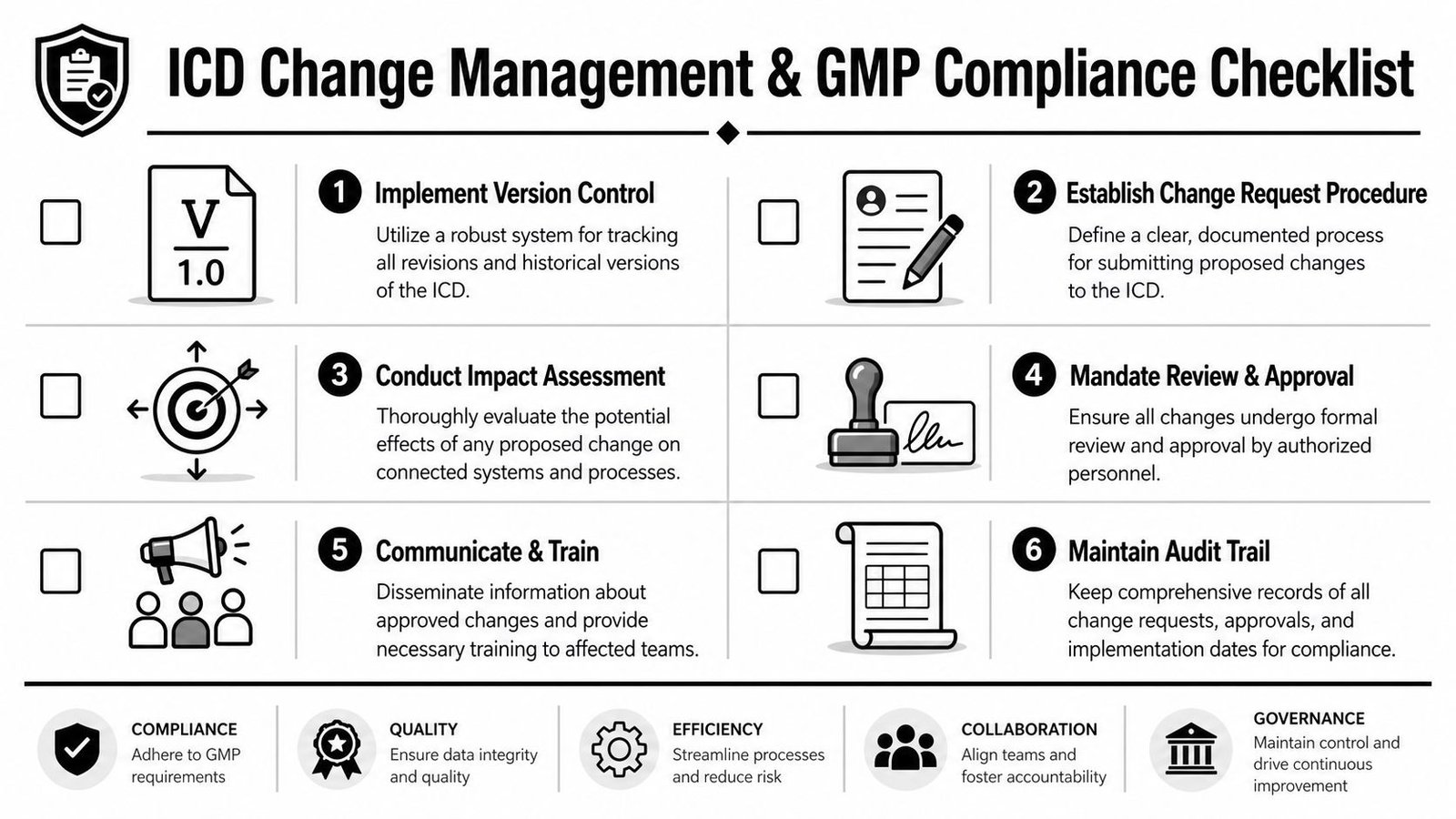
That is why the ICD needs a custodian for each interface and a formal control board to review and approve changes. In medical device manufacturing, this mechanism directly supports change control requirements by maintaining complete version histories for automation software and allowing teams to compare the current system against validated baselines, as described in the INCOSE paper on managing interface requirements.
If you're operating in a regulated production setting, the connection to GMP in manufacturing is straightforward. You need documented control, approved changes, and traceable evidence that the system still matches the intended validated state.
What disciplined change control looks like
The mistake many teams make is treating the ICD like a reference file instead of a controlled artifact. It gets issued for design review, then someone saves a local copy, updates a tag, and never pushes that change through the official path.
A better approach is simple and strict:
One controlled master
Keep one approved current version in a managed repository. Eliminate side copies as working references.Formal change request
Every change to interface behavior, hardware connection, or message structure should enter a documented request path.Impact review before approval
Ask what the change affects. FAT scripts, software validation, wiring drawings, operator procedures, spare parts, and training can all move when an interface changes.Cross-functional signoff
Engineering alone isn't enough in regulated work. Quality, validation, and affected operations staff should review where appropriate.Released revision with history
Record exactly what changed and why. "Updated signals" isn't revision history. "Changed reject confirm from maintained to pulsed output" is.
Good change control protects schedule twice. It reduces the chance of technical breakage, and it reduces the time spent proving what changed after the fact.
That discipline doesn't slow useful improvement. It keeps improvements from turning into undocumented risk.
Common Pitfalls and Dynamic Interface Control
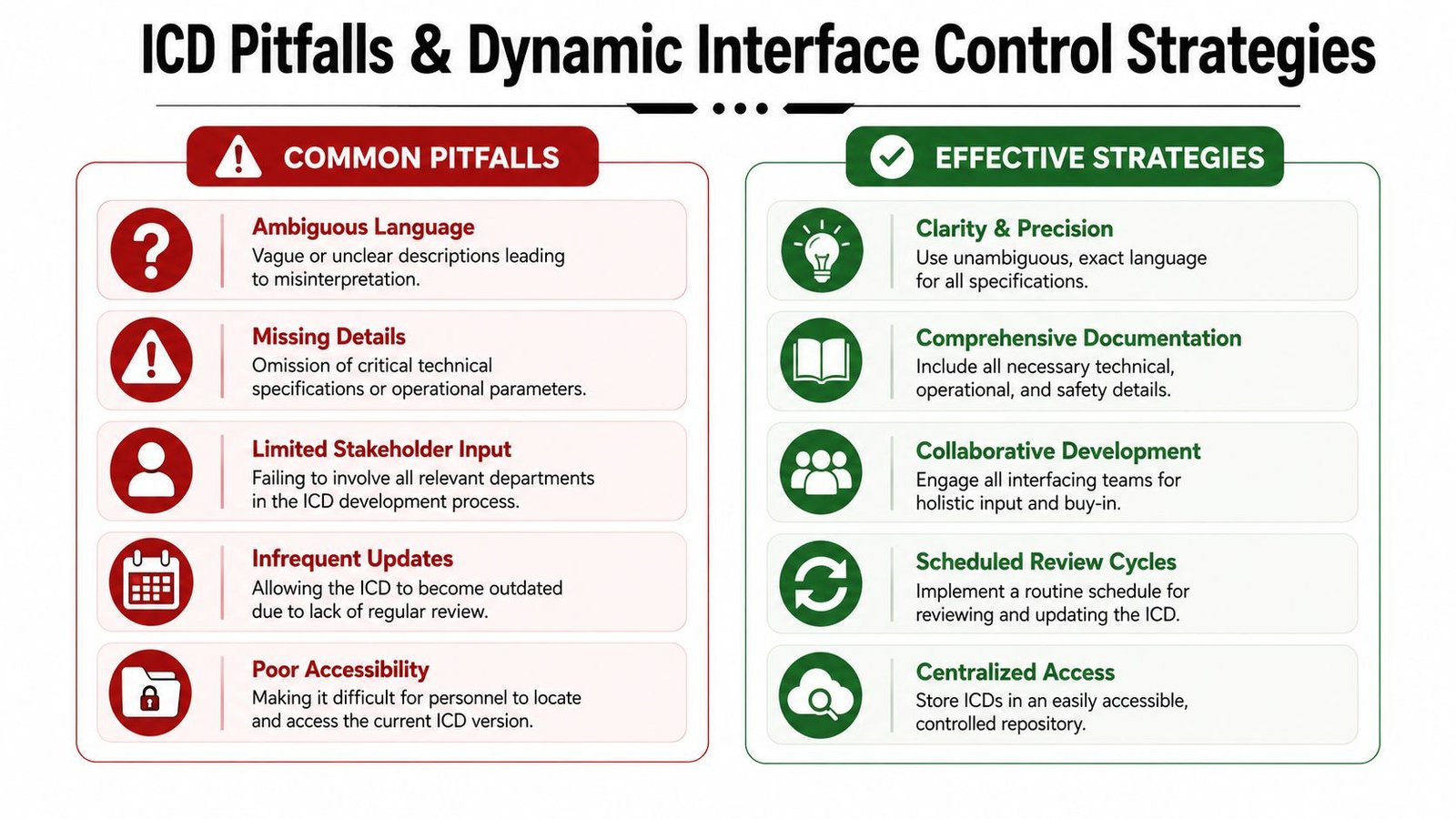
Most ICD failures don't come from missing a title page or using the wrong template. They come from leaving out the details that matter during startup, ramp-up, and long-term operation.
That is why a short ICD can still be a bad ICD. If it doesn't define acceptance, timing, error handling, and operating boundaries, the document may look complete while still failing the project.
The mistakes that keep showing up
Two recurring mistakes carry measurable consequences. Omitting acceptance criteria leads to a 40% increase in Field Acceptance Test failures, and interoperability failures occur in 65% of software-to-hardware integration scenarios when the ICD lacks a defined data schema with sample messages and error cases, according to the analysis of common ICD authoring pitfalls.
Those numbers line up with what many plant teams experience in practice. The project looks fine until site tie-ins begin or until software starts talking to hardware under real operating conditions.
The most common gaps are usually these:
Acceptance criteria missing
The team knows what the interface should do in general, but nobody wrote what counts as pass or fail.Schema details left vague
Message names exist, but field formats, sample payloads, and error cases don't.Physical handshake underdefined
Teams document that two devices connect mechanically, but they don't define enough about tolerances, pinouts, mating conditions, or installation constraints.Design rationale missing
When a future engineer changes one side of the interface, they can't tell why the original tradeoff was made.
Static specs are not enough
In semi-automated manufacturing, standard ICD practice often falls short. Many documents are good at static form, fit, and function. They are weaker at documenting how interfaces behave under motion, load variation, time dependence, and repeated operation.
That gap matters more than it used to. Semi-automated systems often combine moving fixtures, operator actions, servo motion, sensor confirmation, and software logic that adapts to product variation. A static pinout and a connector callout won't fully describe whether the interface remains reliable over time.
NASA-related guidance notes a gap between traditional static analysis and the needs of systems with dynamic operational behavior, and it also states that 60% of integration failures in complex systems stem from unanticipated interface behaviors under operational stress, as discussed in the NASA technical paper on interface issues.
For manufacturing, documenting dynamic interface control means adding items such as:
| Dynamic factor | What to define in the ICD |
|---|---|
| Motion timing | State transitions, delays, debounce logic, and handshake windows |
| Variable loads | Allowed performance range under product or tooling variation |
| Drift over time | Inspection points, recalibration triggers, and wear-sensitive boundaries |
| Error recovery | Safe retry logic, timeout behavior, and operator intervention points |
Static compatibility gets equipment connected. Dynamic compatibility keeps it running.
A mature ICD for modern production equipment should document not only how systems meet at rest, but how they interact during actual operation. That is where long-term reliability lives.
Manufacturers don't need more paperwork. They need documentation that prevents avoidable startup problems, supports GMP-aware change control, and makes semi-automated systems easier to run, maintain, and scale. If you're planning new equipment, upgrading a workstation, or integrating controls across an existing line, System Engineering & Automation provides practical engineering and automation support built around real production constraints.