“Choose electric for efficiency and pneumatic for low cost” is common advice, but it can produce the wrong equipment specification. A cheap cylinder isn't a cheap motion system if you must install compressed-air infrastructure. Equally, replacing a lightly used clamp with a servo can add controls and validation work without improving production.
The useful comparison of pneumatic vs electric actuators starts with the complete machine cycle and the utilities your plant already owns. Define the required motion, measure movement and dwell, then compare installed cost, energy per completed cycle, maintenance, and failure behaviour. That's how you choose equipment that improves the line rather than just its component specification.
Table of Contents
- Pneumatic and Electric Actuators Side by Side
- How Each Actuator Produces Motion
- Energy Use and Running Cost Over a Machine Cycle
- Precision, Repeatability and Speed Compared
- Total Cost, Maintenance and Integration Over the Line's Life
- Manufacturing Use Cases Where Each Actuator Fits
- Failure Behaviour and Validation on Power or Air Loss
- Choose Your Actuator by Situation and Confirm Before You Buy
Pneumatic and Electric Actuators Side by Side
Neither actuator wins every criterion. Choose criterion by criterion, using the requirements of the station.
Pneumatic vs electric actuators on core criteria
| Criterion | Pneumatic actuator | Electric actuator |
|---|---|---|
| Positioning control | Two positions set by end stops or cushions; mid-stroke control needs extra valves and sensors | Programmable position, speed and force profiles |
| Speed | Very fast for simple, fixed-stroke motion | Fast with tuned motion profiles, set in software |
| Energy efficiency | Commonly 10–30% at system level, including the compressor | Often reported near 75–80% |
| Force and overload tolerance | Tolerates overload and absorbs some misalignment through air compliance | Programmable force; needs drive protection against overload |
| Upfront cost | Lower price per cylinder, but needs compressor, dryer, filters and piping | Higher actuator-package price; include drive and controller in the quote |
| Maintenance | Seals, filters, specified lubrication and leak checks | Often fewer service points; drive, encoder and mechanical checks remain |
| Control integration | Valves, sensors and I/O islands; basic arrangements provide limited feedback | Digital control, feedback and diagnostics with suitable drive and sensors |
| Harsh-environment suitability | Robust options for dust and heat; seals and air quality still matter | Requires suitable sealing, materials and thermal management |
The efficiency ranges are typical system-level estimates, not guarantees. They include compressed-air generation rather than comparing only a cylinder with a motor.
The surprising cost row is upfront cost. A cylinder and valve can be inexpensive, but they aren't a complete installation. Conversely, don't assume an electric actuator's advertised price includes its drive, feedback device, cables and controller. Ask for a complete working package.
Force also needs careful interpretation. Pneumatic compliance can soften contact, but it doesn't make poor alignment acceptable. Electric force control offers more adjustment, but motor-current estimation isn't automatically equivalent to measuring force at the tool.
Shortlisting rule: Select the few criteria that constrain production before comparing catalogues.
For a fixed-stroke ejector, those might be cycle time, service access and purchase cost. For a recipe-controlled assembly station, they might be positioning tolerance, force verification and traceability. Shortlist against those priorities, then check the remaining requirements before ordering.
How Each Actuator Produces Motion
Consider a workstation that pushes a finished component out of a fixture. With pneumatics, electrical energy first reaches the compressor. Air preparation equipment removes moisture and particles, while a regulator establishes the operating pressure.
The pneumatic supply and control chain looks like this:
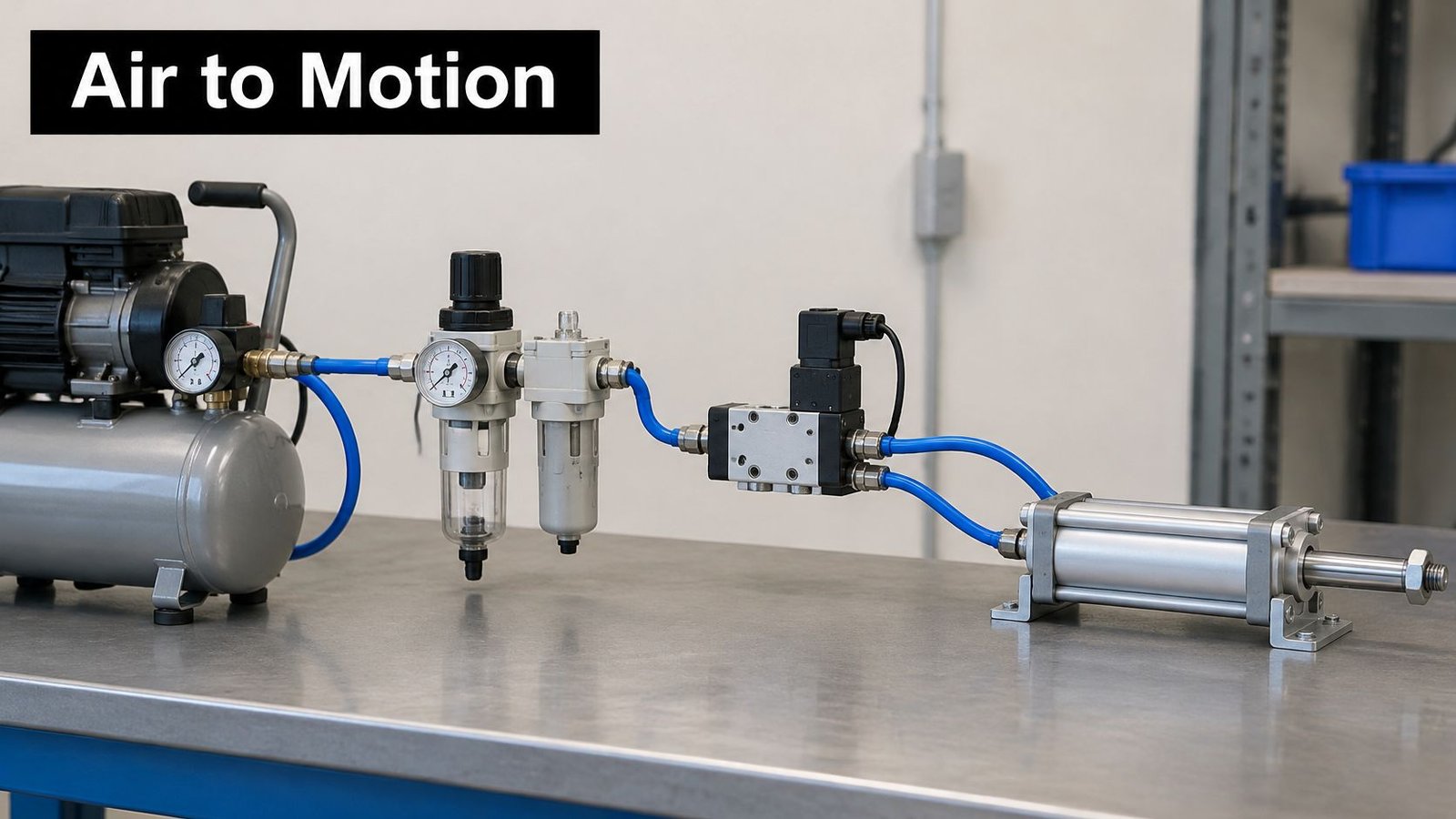
A PLC output energizes a solenoid valve, which directs air to one side of the piston and exhausts the other. The rod extends until it reaches its defined endpoint; switching the valve reverses the movement. End stops establish travel limits, while cushions decelerate the piston near the ends.
Because air compresses, the cylinder has some compliance during contact. Set pressure and flow controls deliberately: increasing pressure to fix slow travel can increase contact force without addressing a restrictive valve or undersized tube.
From a motion command to motor movement
For an electric version, a drive supplies a motor, often a servo or stepper. The motor turns a screw, belt or rack to move the load; a direct-drive linear motor produces translation without that rotary transmission.
In a closed-loop system, an encoder returns position information and the controller adjusts the command. Not every stepper arrangement includes feedback, so specify it rather than assuming it's present.
This demonstration provides another view of actuator operation:
The practical distinction is valves and mechanical endpoints versus programmable motion with feedback. If the tool must stop at changing intermediate positions or change speed during travel, electric actuation is the natural starting point. For repeated in-and-out movement between fixed ends, pneumatic simplicity remains attractive.
Energy Use and Running Cost Over a Machine Cycle
Energy is the clearest quantitative difference.
A pneumatic system converts electricity into compressed air before producing useful movement. Compressors, treatment equipment, distribution pressure drops, valve restrictions and exhaust all contribute to the energy required for a completed stroke. An electric actuator avoids that compressed-air chain, although its drive, motor and transmission still have losses.
A peer-reviewed comparison in Scientific Reports discusses overall pneumatic efficiencies of roughly 10–30%, compared with electric actuator systems often reported near 75–80%. Treat those as ranges shaped by operating conditions, not savings predictions for your machine.
The energy paths explain why purchase price alone is misleading:
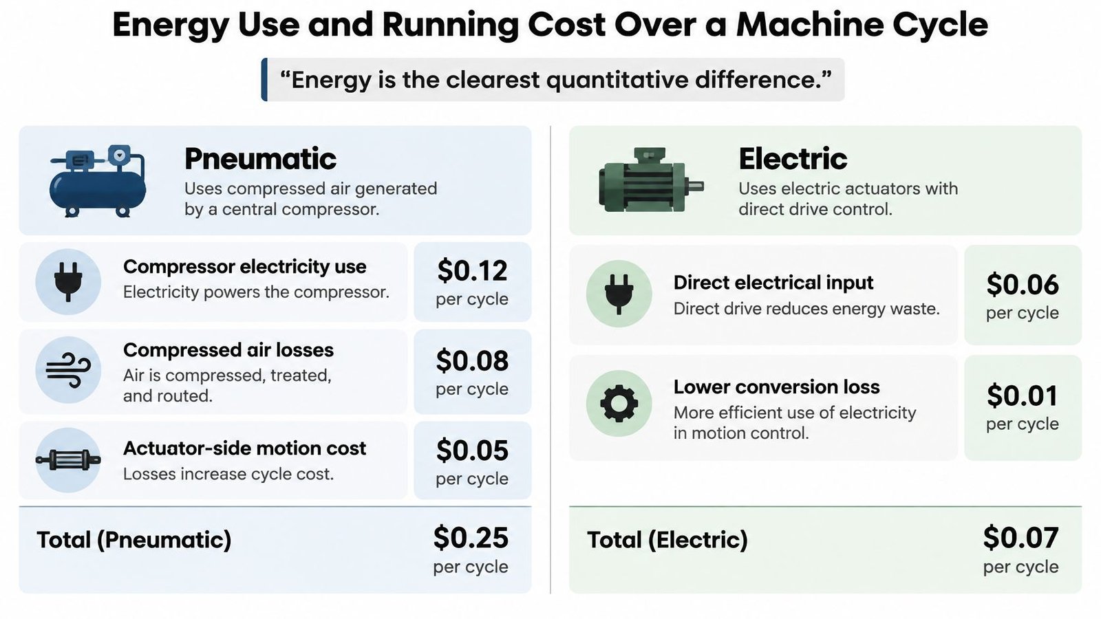
For pneumatic compressor electricity use, electricity powers the compressor. Compressed-air losses occur as air is compressed, treated and routed; those losses increase the actuator-side motion cost per cycle. For electric direct electrical input, the shorter conversion chain can reduce energy waste, but holding current and controller standby consumption still belong in the calculation.
Frequent movement can make the pneumatic energy burden substantial. Idle periods need more careful treatment: a leak-free stationary cylinder isn't necessarily consuming air continuously, whereas leakage, continuously energized valves and the wider compressor installation can still consume electricity.
Measure the complete cycle
Use a power logger for electrical input and a suitable flow meter at the pneumatic branch. Record production state alongside measurements so that blocked cycles, waiting time and normal operation don't get mixed together.
- Log production activity. Record completed cycles per shift, average travel, load and the actual motion sequence. Include rejected or aborted cycles that consume energy without producing an accepted part.
- Capture idle behaviour. Measure dwell, holding and standby periods. Check whether the motor remains energized, valves stay powered, or air continues flowing when the station waits.
- Calculate cycle energy and cost. Divide the attributable measured kWh by completed cycles, then multiply kWh per cycle by the local electricity tariff. For pneumatics, relate branch air consumption to the compressor installation's measured electricity use rather than assigning the whole compressor load to one cylinder.
- Test an equivalent electric option. Match force, travel, speed, dwell and holding requirements. Include drive standby, braking arrangements and any cooling equipment.
Don't compare a loaded pneumatic installation with an unloaded electric demonstration. Both options must perform the same job under representative production conditions.
Also distinguish allocated energy cost from avoidable electricity consumption. Reducing air demand won't necessarily reduce compressor input in direct proportion if the compressor spends more time running unloaded. Whether the plant already supplies other air users changes the investment case.
Precision, Repeatability and Speed Compared
Precision is where the tool stops. Repeatability is how consistently it returns there. Speed is how quickly the complete operation finishes. Treating them as one specification makes it easy to buy unnecessary motion capability or miss a process limitation.
A pneumatic cylinder can repeat reliably against a properly designed mechanical stop. Problems arise when the process needs adjustable intermediate positions, controlled approach speeds or several product recipes. Adding stops, sensors and specialized valves can address those needs, but the original simplicity starts to disappear.
Electric motion makes those adjustments easier to command. However, an encoder reading at the motor doesn't eliminate screw backlash, fixture deflection or thermal movement at the part. Specify the required result at the tooling, not just the drive resolution.
Compare throughput, not unloaded travel
A cylinder can move rapidly over a short fixed stroke. An electric actuator can also be fast when acceleration, deceleration and settling are tuned to the load. Neither achieves useful throughput if the part bounces, the fixture vibrates or the next operation must wait for settling.
The control examples in servo motor applications help identify where programmable movement is useful. During selection, include tool engagement, sensor confirmation and downstream readiness in the timing test.
In a single vendor-documented cotton-swab manufacturing comparison, LinMot reports actuator energy use reduced to 3.2% of the pneumatic level, machine speed increased by 35%, and estimated annual electricity consumption of 21,250 kWh versus 680 kWh, using an 800 mm travel-per-cycle and 900 ms cycle-time basis.
Cotton-swab case: pneumatic cylinders vs linear motors
| Metric | Pneumatic cylinders | Linear motors |
|---|---|---|
| Actuator energy use | Reference level | 3.2% of pneumatic level |
| Machine speed | Baseline | 35% faster |
| Annual electricity | 21,250 kWh | 680 kWh |
| Basis | 800 mm travel, 900 ms cycle | Same calculation basis |
That's a useful application example, not a universal replacement ratio. A direct-drive linear motor also shouldn't be treated as interchangeable with every screw-driven electric cylinder.
Ask whether the process needs a controlled position or only an endpoint. Then measure the full cycle with representative parts at the intended production rate. Buying more positioning capability won't help if loading or inspection remains the bottleneck.
Total Cost, Maintenance and Integration Over the Line's Life
The purchase-price trap starts with comparing a bare cylinder against a complete electric package. For a new pneumatic installation, include the compressor, dryer, filters, regulators, valves, piping and electrical controls. For electric motion, include the motor, transmission, drive, controller, cables, programming and protective equipment.
An existing plant-air system changes that comparison. Its original purchase cost is already committed, but available capacity, pressure stability and incremental maintenance still matter. A retrofit that avoids another compressor is different from one that pushes the utility beyond its usable capacity.
Separate existing infrastructure from new spending
Build the total cost of ownership around the same production requirement and ownership period. Include installation labour, commissioning, operator training and the production interruption needed for the change.
An industry actuator comparison from MarketsandMarkets highlights infrastructure, utilization and maintenance as factors in lifecycle economics. Use those factors to structure the quotation, rather than treating a generic energy-cost ratio as your payback calculation.
A pneumatic retrofit may be sensible when the manifold, tubing routes and maintenance skills already exist. Electric conversion becomes harder to justify if the station runs infrequently and the project requires a new controls platform for a minor function.
Maintenance and integration are part of the package
Pneumatic maintenance includes seal condition, filter servicing, leak detection and lubrication where the equipment manufacturer specifies it. Don't add oil indiscriminately to components intended for non-lubricated service.
Electric actuators still require mechanical attention. Check screws, belts, bearings, couplings and lubrication requirements, alongside encoder connections and drive faults. Keep parameter backups and manage firmware changes so a replacement drive doesn't become an extended troubleshooting exercise.
- Feedback requirements: Specify the position, current, force or fault information the PLC and HMI need. Pneumatic feedback may require additional sensors and a suitable valve island.
- Service capability: Match the equipment to the technicians who will diagnose it. Include drawings, software backups and replacement procedures in handover.
- Upgrade scope: Keep useful existing equipment where it meets the requirement instead of replacing an entire station to change one movement.
At SEA, we upgrade customers' electronic and pneumatic controls to improve performance, improve reliability or meet new production demands. That work can involve fixtures, conveyors, vision systems or PLC-based controls without robotics. Actuator selection isn't a robot decision.
Require these cost lines in every quotation: complete installed capital, compressed-air or electrical energy, and maintenance labour hours. Keep downtime assumptions visible rather than hiding them in a single payback figure.
Manufacturing Use Cases Where Each Actuator Fits
Duty cycle can reverse a seemingly obvious choice. A peer-reviewed reciprocating-actuator comparison, using a 25 mm model actuator, found relatively fixed electric controller and holding demand, little pneumatic dwell consumption apart from valve actuation and leakage, and lower electric energy consumption at continuous operation.
Use that result directionally. It supports checking motion and waiting time separately, not assigning a universal efficiency to every clamp or indexing mechanism.
Best-fit actuator by manufacturing application
| Application | Better fit | Reason |
|---|---|---|
| Two-position clamping of a fixture | Pneumatic | Simple, fast holding with little dwell consumption when leakage is controlled |
| Ejecting or pushing parts off a station | Pneumatic | Fast binary motion with compliant contact; set force and speed to protect parts |
| Pick-and-place to variable positions | Electric | Programmable positions and profiles without additional mechanical stops |
| High-cycle indexing | Electric | Repeatable programmed movement and a strong energy case at high duty |
| Continuous reciprocation with little stop time | Electric | Avoids repeated compressed-air conversion and exhaust losses |
| Pressing or torque-controlled assembly | Electric | Programmable force or torque with suitable sensing and transmission |
| Medical-device station with cleaning exposure | Design-specific selection | Review sealing, cleanability, particles and validation requirements |
| Positioning plus clamping on one station | Hybrid | Electric positioning with pneumatic devices for simple holds |
For pressing, distinguish commanded force from verified process force. If product acceptance depends on a force-displacement signature, specify the appropriate sensor and recording method. Torque-controlled assembly likewise needs a suitable rotary drive or spindle, not merely a linear actuator.
Match the architecture to the operator's work
A semi-automatic station can automate assembly, packaging, inspection or testing while the operator retains control of the process. Pressing and dispensing can also be automated within an operator-loaded workstation. The important question is which repetitive action needs control, not whether the whole workstation can run unattended.
For lower demand or frequent product changes, we offer manual systems customized to the client's exact needs, with more adaptability than rigid automated setups. A well-designed fixture may resolve the quality problem without powered motion.
Medical-device and GMP-aware equipment adds another selection layer. Review:
- Cleaning exposure: Confirm housing seals, materials, lubricant containment and compatibility with the cleaning procedure.
- Product protection: Evaluate exhaust direction, particle generation and surfaces where residue can collect.
- Validation scope: Define recipe access, software change control and the evidence needed after modifications.
A hybrid station can reserve electric motion for recipe-critical positioning and use pneumatic devices for clamping or ejection. Map each station function to the table, then mark the functions that need additional cleaning, safety or validation review before selecting hardware.
Failure Behaviour and Validation on Power or Air Loss
A safe state must be designed, not inferred from the actuator type. A correctly selected spring-return pneumatic cylinder can move toward a defined safe position after pressure is removed, but trapped air, valve state and external loads affect the outcome. Verify the entire stopping movement against guards and pinch points.
An electric axis may lose active holding torque when power disappears. Some transmissions resist backdriving; others don't. Where a load can fall or drift, specify suitable brakes or mechanical restraints and a safety-rated stopping arrangement. A standard drive-enable input alone isn't a complete safety function.
Verify each failure state
- List credible faults. Include electrical power loss, air loss, controller fault, interrupted feedback and unexpected restoration of utilities.
- Confirm the safe response. Compare actual movement with the risk assessment, including residual pressure and gravity loads. Test controlled restart as well as stopping.
- Record controlled settings. Identify force limits, motion parameters, software versions and safety settings that require change control and possible revalidation.
Pneumatic compliance and programmable electric force limits can protect parts, but neither replaces safeguarding. Software process limits aren't automatically safety-rated limits. Hybrid stations require separate assessment of both actuator systems and their interactions.
Choose Your Actuator by Situation and Confirm Before You Buy
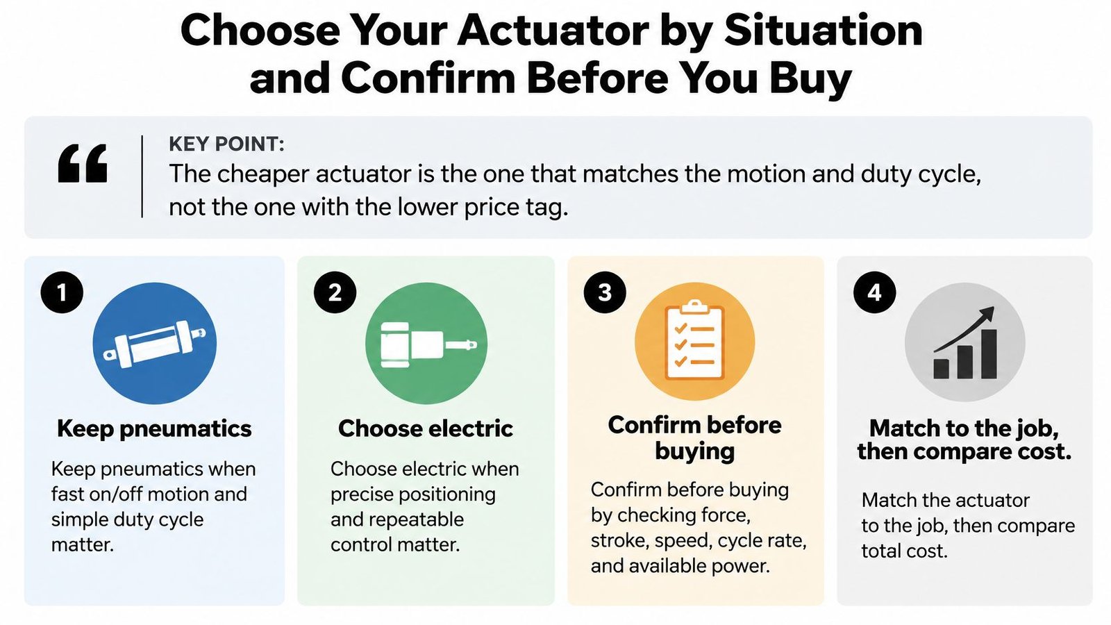
The cheaper actuator is the one that matches the motion and duty cycle, not the one with the lower price tag.
Keep pneumatics when travel is fixed between endpoints, utilization is modest, plant air has usable spare capacity and capital is constrained. Don't replace a functioning binary movement merely to standardize on servos.
Choose electric when recipes require changing positions, production involves frequent or continuous movement, or the process needs recorded motion and diagnostic feedback. Don't specify it solely for precision if a mechanical stop already establishes the required result.
Use this selection guide to frame the decision:
Confirm the specification before committing
A hybrid is appropriate when different functions have different requirements. Keep the architecture understandable for maintenance, and avoid adding another technology unless it delivers a measurable production benefit.
Bring the following to the equipment review:
- Motion and load: Required force, stroke, orientation, speed, positions and repeatability at the tool.
- Production timing: Target cycle time, measured stop time, utilization and representative product variants.
- Utilities: Available electrical supply, compressed-air capacity, operating pressure and measured leakage.
- Ownership costs: Energy per completed cycle, service access, in-house maintenance skills and critical spares.
- Quality and safety: Acceptance criteria, safe states, cleaning exposure and regulated change-control requirements.
Write these requirements into the acceptance plan. Use factory acceptance tests to verify representative operation, operator interaction, recovery from faults and the agreed cycle-time target before installation becomes a production dependency.
Our first consultation is free and carries no obligation to buy. We advise whether a fully automated system is necessary, and we can design tooling that upgrades a manual system to semi-automatic operation as demand increases, without a complete overhaul.
Bring your cycle measurements, utility information and quality requirements to that conversation. If you haven't measured energy yet, bring the motion sequence and production schedule so the assessment can begin with a realistic test plan rather than an assumed saving.
System Engineering & Automation offers custom tooling, fixtures, semi-automatic equipment and electronic and pneumatic control upgrades to help manufacturers improve production. Visit System Engineering & Automation to arrange a free, no-obligation consultation and review which actuator architecture fits your station, existing utilities and budget.