
Your purchase order for a semi-automatic assembly station landed three weeks ago, and the drawing file already runs to forty sheets. Somewhere inside it sits a clamp position that two engineers describe differently, a sensor labeled one way on the layout and another way on the schematic, and a fixed guard that will foul the maintenance door once the frame is welded.
None of that is unusual. Equipment projects rarely fail on machining quality. They fail on the information wrapped around the machined parts. Requirements nobody wrote down, tolerances applied to the wrong features, guarding sketched after fabrication, and drawings that only make sense to the person who drew them.
Process equipment design and drawing is the practice of closing those gaps before steel is cut. It treats the drawing set as the controlling definition of the machine for fabrication, inspection, safety and validation, and as the operating document for the people who run and repair it. Get it right and the build is uneventful. Get it wrong and every downstream stage absorbs the cost, usually with interest.
What follows is the lifecycle a plant team walks through, with the outputs, sign-offs and trade-offs at each stage, and the drawing habits that keep a project out of rework.
Table of Contents
- The Seven Phases Every Equipment Project Passes Through
- Setting Requirements and Choosing the Automation Level
- The Drawing Set a Complete Package Contains
- Tolerances That Protect Function, Not Just Fit
- Safety and Validation Built Into the Drawings
- Drawings Operators and Maintainers Can Use
- From Released Drawing to Installed Equipment
- Confirm the Design Path Before You Order Parts
The Seven Phases Every Equipment Project Passes Through
A team receives a purchase order for a semi-automatic assembly station and starts drawing the same week. The frame profile is chosen, the fixture plate is modeled, guarding is sketched in. Then the first review asks two questions nobody can answer: what cycle time was promised, and does the operator load the part by hand or through a feeder? The fixture plate gets redesigned, the guard moves, and two weeks of drawing time disappears.
That sequence repeats because drawing is the most visible work on a project and the easiest to start early. A phase structure with a named output and a hard sign-off at each gate costs a fraction of one redesign.
| Phase | Main output | Sign-off before moving on |
|---|---|---|
| 1. Requirements capture | User requirement specification with volume, cycle time and footprint | Customer and production lead |
| 2. Concept development | Two or three layout options with rough cost and footprint | Customer review and selection |
| 3. Detailed design | 3D model, mechanical, electrical and pneumatic design | Engineering review of interfaces and safety |
| 4. Manufacturing drawings | Released drawing set and bill of materials | Design approval and drawing release |
| 5. Procurement and fabrication | Purchased parts, machined and assembled frames | Inspection against drawings |
| 6. Acceptance, installation and commissioning | Test records and signed acceptance | Factory and site acceptance tests |
| 7. Revision and maintenance | Controlled revisions and maintenance records | Change approval for every modification |
The cost of changing a decision multiplies at every phase. Moving a sensor in the 3D model takes minutes. Moving it after the bracket is machined takes a new bracket, a new wire route, a new drill schedule and a new inspection report.
Practical rule: If two people describe the machine's cycle differently, the project is still in requirements capture, whatever the schedule claims.
Cross-functional review is not a formality. FDA process-validation guidance treats validation as a lifecycle activity and recommends an integrated team covering process engineering, manufacturing, quality assurance and statistics, with those disciplines contributing before drawings are finalized (FDA guidance on process validation). The same logic holds in an unregulated plant: the technician who will service the machine should see the layout before the frame is ordered.
Which Phase to Check First on a Live Project
Start with phase one, not phase four. Pull the requirement specification and check three things: is there a number for cycle time, is there a named person who owns the operator interface, and is the regulatory scope written down. If any of those is missing, adding detail to the drawings won't rescue the project. It will just make the rework more expensive to document.
Setting Requirements and Choosing the Automation Level
Vague requirements are the most expensive line item in an equipment budget, because they get paid for in drawing rework rather than in the requirement document itself. Fix the inputs before anyone models a bracket: target output per shift, cycle time, product variants, the skill level of the operator you can hire, and the quality standard the output has to meet.
Those five inputs decide which automation level you're buying. Choosing the level late is how a plant ends up with a fully automated cell it can't staff or a manual station that bottlenecks at 60% of forecast demand.
Matching controls and validation effort to real production risk is a design decision, not a paperwork exercise. FDA's Quality System Regulation is built to scale with the device's risk, process complexity, manufacturing activities and the manufacturer's size and organizational complexity, and it is framework-based rather than prescriptive (FDA overview of the Quality System Regulation). A manual workstation upgrade doesn't need the same controls as a high-volume automated line, but both have to control the processes that affect product quality.
Three Levels, Three Different Drawing Scopes
| Automation level | Best fit | What the drawing set adds | Main tradeoff |
|---|---|---|---|
| Manual with improved fixtures | Low demand or a quality upgrade of an existing manual process | Fixture and tooling drawings, few control schematics | Lowest validation effort and highest labor dependence |
| Semi-automatic | One defined task whose demand may grow | Layout, sensors, pneumatic diagram and interlocks on the existing frame | Custom to one task and upgradeable without a full overhaul |
| Fully automated | High volume, fewer operators, or a safety-driven reduction of manual motion | Controllers, recipes, alarms, user access and data logging as well as the mechanical set | Lowest labor dependence and the highest controls and validation effort |
A manual cell is usually the right recommendation when demand is low or when the customer wants better quality than a traditional manual operation delivers. The interesting middle case is the upgrade: a manual station that gains a locating fixture, a clamp and one sensor, becoming semi-automatic without replacing the frame. We design tooling for exactly that move when production demands rise, so the customer buys capability rather than a new machine.
Concept development is where the customer gets to change their mind cheaply. After a purchase order, concept work begins and the customer can review and revise the layout before anything is finalized. Two or three options, each with a footprint and a rough cost, do more to sharpen a requirement than another round of meetings.
Three questions worth answering in writing before concept work starts:
- What happens to the line when this machine stops for an hour? The answer sets your recovery and changeover requirements, which shape tooling and access.
- Who loads it, and what else are they doing at the same time? Operator attention drives sensor choice and cycle design more than headcount does.
- Which document proves the machine was built as specified? If nobody names one, the acceptance test will be improvised.
The Drawing Set a Complete Package Contains
A process equipment drawing package is not one drawing. It is a set of linked documents, and the standards that govern it split along two lines. General drafting practice controls how information is prepared and revised, while drawing-type rules define how layouts, assembly drawings, detail drawings and schematics are used. ASME Y14.100 sets the essential requirements for preparing and revising engineering drawings and associated lists, and it was adopted for U.S. Department of Defense use on January 30, 1998; ASME Y14.24 covers types and applications of engineering drawings and was adopted for DoD use on February 14, 2000, with its 2020 edition issued on October 23, 2020 (ASME Y14 standards).
That structure is what keeps a package coordinated when several disciplines touch it, which is the normal case on a semi-automatic station with mechanical, electrical and pneumatic content.
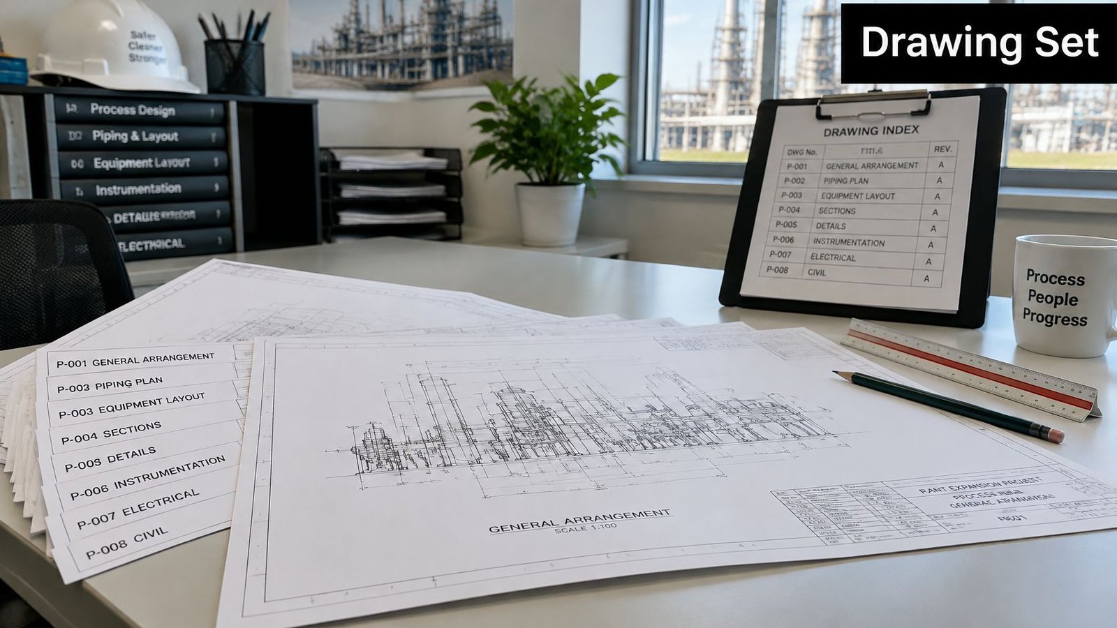
| Document | What it shows | Main users |
|---|---|---|
| Layout drawing | Equipment footprint, access routes and clearances | Plant layout team and maintenance |
| Assembly drawing | How parts fit together and in what order | Assemblers and fabricators |
| Detail drawing | Individual part dimensions, tolerances, material and finish | Machinists and inspectors |
| Electrical schematic | Power distribution, control wiring and I/O list | Controls engineers and electricians |
| Pneumatic diagram | Air circuit, valves, regulators and actuators | Maintenance technicians |
| Bill of materials | Every purchased and made item with quantities | Procurement and cost estimators |
| Tooling and fixture drawing | Locating pins, clamps and sensor positions | Toolmakers and operators |
Why Coordination Beats Precision
The documents only work as a set. A mechanical change can move a bracket and leave a proximity sensor outside its detection zone. A valve swap can change the sequence timing that the pneumatic diagram documents and the controls program assumes.
Take a semi-automatic station where the layout shows two clamps at the operator load position and the pneumatic diagram shows three, because a third clamp was added for a stiffer part variant and the layout wasn't updated. Fabrication builds to the layout, the machinist skips the third clamp's tapped holes, and the omission surfaces at the factory acceptance test when the part won't locate consistently. A revision check across the layout, the pneumatic diagram and the fixture drawing catches it before any metal is cut.
If your drafting conventions aren't settled, a reference on manufacturing drawing standards is worth reading before the first sheet is issued, because retrofitting convention onto a live package is how revision letters get out of sequence.
Two rules prevent most of these conflicts:
- Every BOM item appears on a detail drawing or a purchase record. An orphan part number on the bill of materials is either a phantom or an undocumented purchase, and both cost money.
- Every revision letter appears on every related sheet. A package where the assembly drawing is at revision C and the pneumatic diagram at revision A is not a controlled set.
- The drawing index lists the current revision of each sheet. Anyone opening the file can then tell within a minute whether they're looking at the built configuration.
Tolerances That Protect Function, Not Just Fit
Two opposite mistakes cost the same money. Over-tolerancing every feature raises machining and inspection cost without adding capability, because the shop spends time chasing precision the machine doesn't need. Under-specifying the locating surfaces and hole patterns lets stack-up accumulate until parts misalign, bind, leak, or present inconsistently to the next operation.
Geometric dimensioning and tolerancing exists to settle that argument in functional terms. The ASME Y14.5 standard was first published in 1957 covering dimensioning and notes, and it evolved into the modern standard for geometric dimensioning and tolerancing, defining symbols, rules, definitions, requirements, defaults and recommended practices (ASME codes and standards chronology). By 1995, ASME Y14.5.1M added mathematical definitions of dimensioning and tolerancing and explicitly supported CAD and CAM, which is why a tolerance on a modern drawing is a computable statement rather than a note.
NIST defines a tolerance as the total permitted variation of a dimension, and it makes a point that belongs on every drawing review: inspection results only mean something when manufacturing deviation is evaluated together with measurement uncertainty (NIST technical note on dimensional tolerancing).
A Sequence for Applying Tolerances
- Establish functional datums first. Take them from the load path, the tooling nest, the product interface or a shaft centerline, not from whichever face was easiest to dimension.
- Mark the critical-to-function features. The hole pattern that locates a part and the clamp face that holds it qualify. The frame's overall length usually doesn't.
- Apply position, orientation or profile controls to those features only. Controls on non-functional features buy inspection time, not capability.
- Leave the rest as general tolerances or reference dimensions. This tells the shop where to spend effort.
- Confirm each critical tolerance has an inspection method with uncertainty well below the tolerance band. If the tolerance is 0.05 mm and the available measurement can't resolve half of that, the drawing is asking for a decision the plant can't make.
A fixture illustrates why. On a locating-pin pattern, the pin diameter and position control where the part sits, so they carry the tight tolerance. The frame dimensions around the fixture only need to hold the pins in the right neighborhood. Reverse those two and you pay for precision on a part that doesn't affect position while leaving the one that does to stack-up. Running the arithmetic before release is worth the hour; the method is the same one covered in this guide to tolerance stack-up analysis.
Each critical tolerance should survive three questions before release: what function does it protect, which process can hold it, and which measurement proves it.
Safety and Validation Built Into the Drawings
Guarding added after fabrication is the most predictable cost overrun in equipment work. A fixed guard designed around a finished frame can block the maintenance door, swallow the clearance needed to change a belt, or push the operator's reach into a pinch point. The frame then gets cut, re-welded and repainted while the schedule absorbs the delay.
OSHA treats guards and safety devices as two distinct safeguarding methods: guards are physical barriers, while devices interrupt the operating cycle or prevent access during hazardous motion (OSHA machine guarding publication). The same publication requires safeguards to prevent contact, resist removal or tampering, protect against falling objects, and avoid creating new hazards such as sharp edges or shear points. Each of those requirements lands on a drawing as a callout: a dimension, a fastener specification, a switch location. Left to the fabricator, each becomes a judgment call made with a grinder in hand.
The layout and assembly drawings should therefore show the hazard envelope, fixed guards, interlocked access doors, emergency-stop positions, safe-clearance dimensions, and access provisions for cleaning, lubrication, changeover and maintenance. Mark each stored-energy source and its isolation point: pneumatic, hydraulic, electrical, gravitational and thermal. A technician picking up the set years later should find every energy source on the sheets before finding it by accident.
The Semi-Automatic Case
On a semi-automatic station, separate the operator loading and unloading zone from automated motion, use interlocked guarding wherever entry is possible, and enforce one rule in the control design: closing a guard never restarts the machine. Restart requires a deliberate action at the station. Position the reset so the operator can see the guarded zone when pressing it. Unexpected restart drives the worst injuries on this class of equipment, and the interlock drawing is where that restart path gets designed out.
A guard drawing that doesn't show the maintenance access route has only moved the hazard from the operator to the technician.
The Regulated Plant Case
For medical-device manufacturers, the drawing set carries a second job. FDA defines process validation as establishing objective evidence that a process consistently produces a product meeting predetermined specifications, and where later inspection or testing can't fully verify the result, the process must be validated with a high degree of assurance and approved under established procedures (FDA process validation guidance). FDA guidance also requires production equipment to be appropriately designed, constructed, placed and installed to facilitate maintenance, adjustment, cleaning and use.
That turns drawing content into evidence. The package should record equipment requirements, process flow, critical parameters, cleanability, maintenance access and installation details. Software belongs in the same package. FDA guidance states that software used to automate any part of device production or the quality system must be validated for its intended use under an established protocol, covering manufacturing, testing, component acceptance, labeling, packaging, distribution and complaint handling (FDA guidance on software validation). Controllers, recipes, alarms, user access levels and data logging therefore belong in the drawing and specification package, settled before installation rather than negotiated during commissioning.
Change control closes the loop. ASTM E2500 applies a science- and risk-based approach across process equipment, utilities, monitoring, controls and automation, treating specification, design and verification as one continuous activity rather than separate phases. Design validation has to demonstrate conformity to defined user needs under actual or simulated use conditions, with the results documented in the Design History File (21 CFR Part 820). A drawing revision that moves a clamp position needs a path into that record, which is why revision blocks and change notes earn their place on the sheet.
| Drawing feature | Validation evidence it supports |
|---|---|
| Critical dimensions on detail drawings | Capability and tolerance verification during acceptance |
| Material and surface finish callouts | Product-contact conformity and cleanability claims |
| Guard, interlock and e-stop locations | Risk control verification and operator training content |
| Sensor and I/O tagging | Control function testing and software validation |
| Maintenance access clearances | Installation qualification and serviceability checks |
| Revision history | Change control records and revalidation triggers |
Read this way, the table doubles as a lookup index: each row tells the validator which sheet answers which question. A drawing set that carries this content answers those questions from the sheets themselves, which is what keeps a design review from turning into a document chase.
Drawings Operators and Maintainers Can Use
The floor tells you quickly whether a drawing set works. A 2025 manufacturing-skills survey of more than 600 professionals reported that 67% observed a growing skills gap, naming quality control and inspection, technical troubleshooting, equipment maintenance and inadequate training as major concerns, while 80% of manufacturers said labor shortages were disrupting production (The 2025 Manufacturing Skills Report). A drawing set fails when it assumes the designer is still in the building.
Five rules matched to that skill mix:
- Put startup, normal-stop and emergency-stop sequences on a one-page sheet tied to the layout, so recovery doesn't require reading a controls narrative.
- Call out lubrication points, filter and belt intervals, and the tools required directly on the assembly drawing, where a technician is already looking.
- Tag every sensor, valve and guard with the same identifier on the layout, the electrical schematic and the pneumatic diagram. One tag, three sheets.
- Show adjustment direction and acceptable readings beside critical setups such as clamp height or locating-pin engagement, so a gauge replaces a judgment call.
- Mark pneumatic, electrical and gravity lockout points next to the access door they protect, which is the moment a technician needs them.
Picture a new operator on a semi-automatic station. They match the clamp-sensor tag on the layout against the pneumatic diagram and the guard label, confirm the part-present reading on the sensor, and only then start the cycle. That's a drawing set doing operational work.
The release question: can a technician who never met the designer service this machine from the drawings alone? If not, the package isn't finished.
From Released Drawing to Installed Equipment
Drawing release is a hand-off, not the end of design. Manufacturing drawings are started after the full design is finalized and approved, and they outline all specifications needed for production. We start ordering purchase items at the same time as work on those manufacturing drawings, so long-lead components don't sit behind the drafting queue.
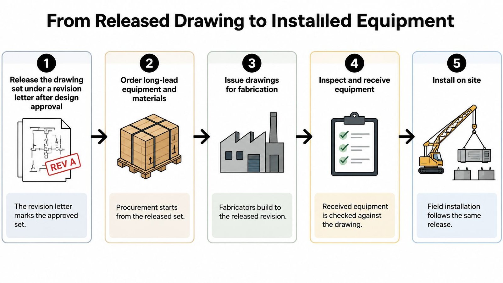
The sequence below is the one that holds up in practice.
- Release the set under a revision letter after design approval. The letter marks the configuration that fabrication is allowed to build. Common slip: issuing sheets individually, so nobody can state the released revision.
- Order purchase items in parallel with the drawings. Waiting for a complete package before ordering adds weeks to every long-lead item. Common slip: ordering against a concept layout, then absorbing change fees.
- Fabricate and assemble against the released revision, with inspection against the detail drawings rather than against a verbal understanding. Common slip: a shop working from a superseded print taped to the machine.
- Run the factory acceptance test using the test records defined back in requirements capture. The acceptance criteria should have been written before the design, not negotiated at the test.
- Install and commission on site, recording every field change as a redline. Commissioning is where access problems, sensor positions and clearance errors surface; capturing them on paper is the only way they get fixed twice.
- Issue a final revision that reflects the as-built equipment. The as-built set is what the next maintenance team will trust.
- Control every later change through the same approval path. An untracked field change makes the drawings wrong, and wrong drawings get ignored, which is worse than no drawings.
Redlines from commissioning follow a fixed route: mark the drawing, log the change, get the approval the original design needed, then reissue. Suppliers shouldn't keep informal copies. A vendor working from their own annotated print produces parts that match their print and not the machine.
A clean handover is easy to recognize. It has a complete drawing set at one revision, a revision history that explains every change, and a bill of materials that matches the parts physically installed. The commissioning of equipment step is where that package either closes or deteriorates.
The same handoff, in five steps, before you apply it to your own file:
Confirm the Design Path Before You Order Parts
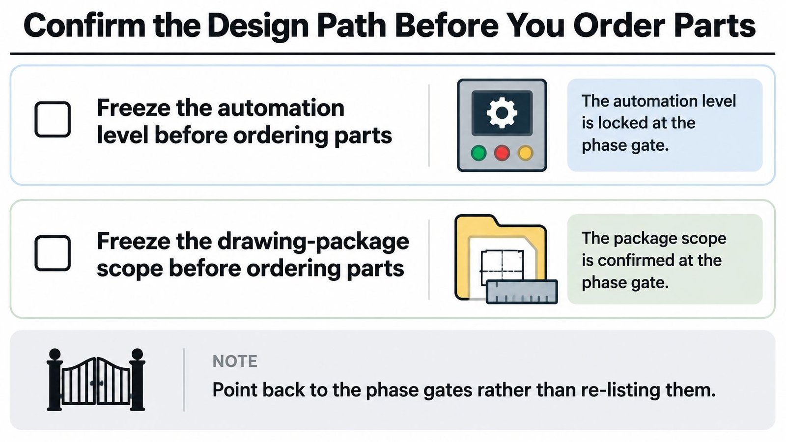
The decision in front of most plant teams isn't whether to automate. In 2025, 95% of surveyed U.S. industrial firms planned to introduce new automation within three years, according to the 2025 U.S. Automation Index summarized by Modern Distribution Management (MDM on U.S. industrial automation). The decision is whether the automation level and the drawing-package scope get frozen before parts are ordered, or discovered during commissioning.
Go back to the gates. Phase one fixes demand and the operator's role. Phase two selects a layout. Phase three freezes interfaces and safety. Order parts before those three are signed and you're buying hardware for a design you haven't finished.
System Engineering & Automation designs new equipment and improves existing manufacturing processes, from a single workstation to a full line. Designs integrate with machines already on the floor so an upgrade enhances the production environment rather than interrupting it, and upgrades are designed to keep equipment competitive as production demands change.
One useful working session: bring cycle time, product variants, floor footprint, and any safety or validation constraint. The output is the concept path for your demand level and the drawing scope that path requires, agreed before a purchase order exists. That conversation is cheapest when nothing has been machined yet.
If a project is already moving, the cheapest review is the one that happens before the purchase order. System Engineering & Automation builds semi-automatic systems, custom tooling and fixtures, and the drawing packages behind them, with mechanical, electrical and controls work on one revision path so your layout, schematic and pneumatic diagram stay coordinated. Visit System Engineering & Automation to put one live project through the phase gates with our team.