A semi-automated cell is running smoothly until the fixture starts rejecting parts that passed the previous operation. The operator checks the CAD model, the machinist checks the print, and quality checks the inspection result. Each person sees a slightly different interpretation because the production drawing doesn't define the datum reference, surface requirement, or inspection method clearly enough. The line stops while engineering, production, and the supplier work out what the designer intended.
That situation is common in manufacturing, especially when a company is upgrading manual workstations, introducing custom tooling, or transferring production between suppliers. A production drawing isn't just a design record. It's the controlled communication document that tells people how to make, inspect, assemble, and release a product consistently.
Production drawings formalized manufacturing communication during the Industrial Revolution, when orthographic projection and scaled engineering conventions emerged in France. The long history of technical drawing includes examples such as a Babylonian castle plan dated to around 2000 B.C., while modern practice is shaped by standards including ASME Y14.5, most recently revised in 2018, and ASME Y14.24, published in 2020 to define engineering drawing types and applications in industry (historical and standards background on engineering drawings).
Table of Contents
- Why Production Drawings Make or Break Manufacturing
- The Six Essential Components of Every Production Drawing
- How Tolerances and GD&T Control Manufacturing Quality
- Standards and Regulatory Requirements for Production Drawings
- Common Mistakes That Undermine Production Drawings
- Production Drawing Release Checklist for Manufacturing Teams
Why Production Drawings Make or Break Manufacturing
A drawing can look complete on an engineering workstation and still fail on the shop floor. A model may show the intended shape, but the production team also needs to know which surfaces establish position, which dimensions control assembly, what variation is acceptable, and how inspectors will verify the result.
Consider a fixture plate for a semi-automated assembly cell. The hole pattern is present in the CAD model, but the drawing gives no functional datum structure. The fixture builder locates the pattern from a convenient edge, while the assembly team references a mating face. Both interpretations produce parts that appear reasonable in isolation. Once the components meet, the alignment error becomes a stoppage rather than a drafting discussion.
Practical rule: If a machinist, inspector, or assembler has to ask which feature controls the setup, the drawing isn't ready for release.
A properly controlled production drawing turns design intent into an authorized manufacturing instruction. It communicates geometry, dimensions, tolerances, materials, finishes, standard parts, assembly relationships, and revision status. That information supports the people who program machines, build fixtures, inspect incoming parts, troubleshoot equipment, and approve changes.
The cost of ambiguity appears in several places:
- Rework begins early: Suppliers pause to request clarification or make assumptions that later require correction.
- Throughput becomes unstable: A single unclear interface can stop an otherwise capable semi-automated line.
- Quality decisions become inconsistent: Different inspectors may apply different interpretations when the drawing doesn't define the control method.
- Change control weakens: Teams may update a model, a drawing, or a work instruction without updating the complete controlled document set.
- Compliance exposure grows: Regulated manufacturers need traceable approvals and controlled production information, not informal explanations passed between departments.
The best drawing isn't the one with the most annotations. It's the one that gives every downstream function the information it needs, in the right document, with no unresolved interpretation left for production to discover.
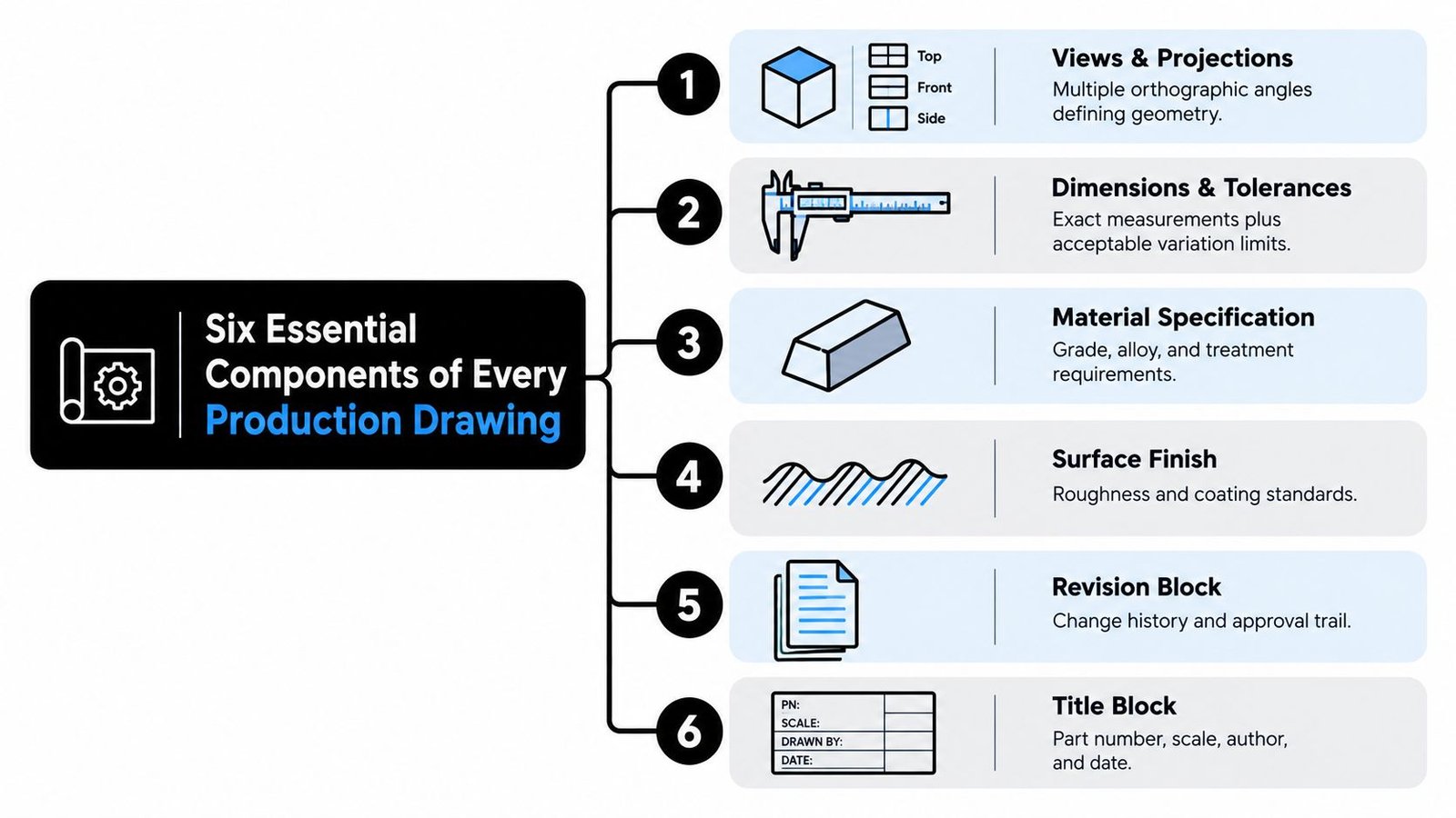
The Six Essential Components of Every Production Drawing
Manufacturing education and practice treat production drawings as complete drawing sets that provide the information needed to make and assemble a product. That includes dimensions, standard parts, bills of material, and assembly views. ASME Y14.100-2013 establishes essential requirements for manual and computer-generated engineering drawings, reinforcing that a drawing needs structure and control rather than visual detail alone (working drawings and assemblies guidance from McGill).
A practical production drawing audit starts with six components.
1. Views and projections
Use orthographic views, sections, details, and auxiliary views to expose every feature that affects manufacture or inspection. A hidden hole, angled face, or internal pocket shouldn't depend on a machinist rotating a model mentally. Show the geometry in a way that makes the intended setup and feature relationship clear.
For assemblies, include an assembly view and identify each item against the bill of materials. Detail drawings should define the individual parts, while the assembly drawing should explain how those parts relate.
2. Dimensions and tolerances
Dimensions define size and location. Tolerances define the permissible variation. Without both, a value on the page can be mistaken for a target rather than a manufacturing requirement.
Put specific limits on functional features, fits, interfaces, and inspection-critical characteristics. General title-block tolerances can support routine features, but they shouldn't replace a deliberately selected requirement where assembly depends on it.
3. Material specification
Name the required material grade, condition, treatment, or certification requirement. “Steel” or “aluminum” may describe a family, but it doesn't give procurement, machining, finishing, or quality teams enough direction for a controlled build.
4. Surface finish
Surface finish affects sealing, sliding, wear, cleaning, appearance, and coating performance. Identify finish requirements on the relevant surfaces, and separate them from general notes when a feature has a functional surface condition.
5. Revision block
The revision block should show what changed, who approved it, and when the change took effect. Link the revision to the affected features, notes, or companion documents so production can determine whether existing stock, tooling, inspection programs, or work instructions remain valid.
6. Title block and controlled references
The title block identifies the part number, drawing title, scale, author, approval status, and applicable conventions. Controlled references should point to specifications, procedures, assembly instructions, or inspection plans when those requirements don't belong on the drawing itself.
A drawing shouldn't become a storage area for every production instruction. Keep direct geometry and feature requirements on the drawing. Place detailed process sequences, operator steps, validation protocols, and inspection procedures in controlled companion documents, then reference them unambiguously. For manufacturers developing custom fixtures, a documented fixture design and manufacturing process helps connect the drawing's functional requirements to the equipment that will hold and locate the part.
How Tolerances and GD&T Control Manufacturing Quality
Exact manufacture isn't achievable in real production. Cutting tools wear, materials move, machines vary, fixtures introduce location error, and inspection equipment has its own capability limits. A tolerance system converts that unavoidable variation into defined acceptance boundaries. Tolerance is the difference between the maximum and minimum permissible limits, while ASME Y14.5 provides authoritative rules for dimensioning and geometric dimensioning and tolerancing, or GD&T (tolerance and GD&T fundamentals).
The engineering decision isn't to make every feature as tight as possible. It's to control the features that determine function and leave non-critical features manufacturable.
Start with function, not convenience
A datum reference frame should reflect how the part interfaces with its assembly, fixture, or inspection setup. If a mounting face establishes height, use that functional relationship. If two holes align a component, control their relationship to the relevant datums rather than dimensioning each hole from unrelated edges.
Poor datum selection creates a familiar dispute. The machined part meets individual coordinate dimensions, but the component still sits incorrectly in the assembly because the drawing never controlled the relationship that matters. GD&T works when it describes how features function together, not when it adds symbols without a clear design rationale.
Match the drawing to the process
Tighter tolerances reduce permissible process variation, but they also increase manufacturing cost and inspection burden. A semi-automated line may need a precise fixture interface, while a cosmetic clearance feature may not need the same level of control. Applying the same restrictive requirement everywhere can make a design expensive without improving performance.
The tolerance scheme should drive the equipment design:
- Fixture strategy: Identify the datums that locate the part and ensure the fixture contacts those functional surfaces.
- Alignment method: Define how the station will detect or correct feature variation before an operation begins.
- Inspection method: Select gauges, vision systems, probes, or coordinate measurement based on the characteristic and its tolerance.
- Process feedback: Decide which measurements confirm capability and which only release the finished part.
- Assembly verification: Check the interfaces that determine whether components fit, not only isolated dimensions.
A drawing that doesn't define the inspection logic leaves quality to interpret engineering intent after production has already started.
Tolerance stack-up analysis is especially useful when several features combine to control a final gap, position, or alignment. It helps the team understand whether individual requirements support the assembly result before the fixture, tooling, and inspection equipment are designed (tolerance stack-up analysis services).
For semi-automated equipment, the drawing should also distinguish between characteristics that the machine controls and characteristics that the operator or quality team verifies. That distinction prevents a common failure mode, where the line is mechanically repeatable but the part remains functionally inconsistent because the wrong features were controlled.
Standards and Regulatory Requirements for Production Drawings
A supplier can machine the geometry correctly and still fail the handoff if line meaning, revision status, or labeling controls remain open to interpretation. Standards give design, manufacturing, sourcing, and inspection teams a shared technical language. ISO 128-1:2020 applies to manual and computer-based technical drawings across fields including mechanical engineering, construction, architecture, and shipbuilding. It also treats technical drawing as the complete documentation package for a product, including workpiece, subassembly, and assembly documentation (ISO 128-1:2020 sample).
ISO 128-2:2020 defines line types, designations, configurations, leader lines, reference lines, and instructions placed on those lines. In production, that consistency removes uncertainty over hidden edges, centerlines, section boundaries, and inspection references (ISO 128-2:2020 line conventions).
| Standard | Scope | Practical application |
|---|---|---|
| ASME Y14.5 | Dimensioning and GD&T | Define feature relationships, datum references, and geometric controls |
| ISO 128-1:2020 | General technical drawing rules | Standardize the structure and graphical communication of technical documentation |
| ISO 128-2:2020 | Lines and leader conventions | Reduce misinterpretation of views, features, and instructions |
| ASME Y14.100-2013 | Essential engineering drawing requirements | Control manual and computer-generated drawing practices |
| FDA labeling requirements | Medical-device design history file labeling documentation | Connect drawings, artwork, inspection, attachment procedures, approvals, and dates |
GMP-aware manufacturers need document relationships that remain clear across engineering, automation, quality, and production. The FDA states that design-history-file labeling specifications require an engineering drawing and/or artwork for each label, together with suitable inspection or control procedures and attachment procedures. Procedures, drawings, and artwork must include the preparer's name, approval signature, and date. Label specifications must identify the substrate, dimensions, ink, finish, and mounting method so the label stays attached and legible through processing, storage, handling, distribution, and use (FDA quality system labeling requirements).
For medical-device equipment, connect the drawing, work instruction, artwork, validation record, and change approval before automation design starts. A semi-automated labeling station may repeat an operation precisely, yet still produce nonconforming output if it uses an obsolete artwork revision or lacks a defined inspection response.
Documented manufacturing drawing standards can align templates, review gates, line conventions, title blocks, and revision practices across sites and suppliers. The purpose is controlled technical communication, with traceability that survives fixture changes, labeling-station updates, and process revisions.
Common Mistakes That Undermine Production Drawings
The most damaging drawing errors are often small omissions. A missing datum, an unspecified finish, or an unclear reference can force a supplier to stop, make an assumption, or produce a part that passes a narrow reading of the print but fails in the assembly.
Mistake 1 Overloading the sheet
An engineering team may place every process instruction, inspection step, and assembly warning on one drawing to keep information together. The result is a crowded document that's difficult to read and harder to revise. Separate detail drawings, assembly drawings, work instructions, and inspection plans when each serves a different user.
Mistake 2 Choosing convenient datums
A CAD origin or easily selected edge isn't automatically a functional datum. If the fixture locates from a mating face but the drawing references another surface, the machine and inspection department may validate different conditions. Choose datums from the part's functional interfaces and confirm the setup with manufacturing before release.
Mistake 3 Using inconsistent line conventions
A supplier shouldn't have to infer whether a line represents a hidden feature, a section boundary, or an instruction reference. Consistent line types and leader conventions reduce clarification loops between engineering, production, and quality.
Mistake 4 Mixing regulated documents without control
Medical-device labeling may require separate artwork, engineering drawings, inspection or control procedures, and attachment procedures. Treating those as informal notes on a detail drawing makes revision status difficult to verify and can break the traceability required for controlled production documentation.
Mistake 5 Omitting inspection criteria
A dimension without a defined inspection approach can still produce disagreement. State the characteristic, reference the applicable standard or procedure, and identify any required inspection record or control method. A production drawing should let quality determine what to measure and why.
Cleaner beats denser: Put each requirement in the document where the responsible person will use it, then control the links between documents.
This approach fits semi-automated lines and legacy suppliers particularly well. Operators need quick visual guidance, machinists need unambiguous feature requirements, and inspectors need a stable basis for acceptance. A shorter, better-organized drawing set often supports those users more effectively than one information-heavy sheet.
Production Drawing Release Checklist for Manufacturing Teams
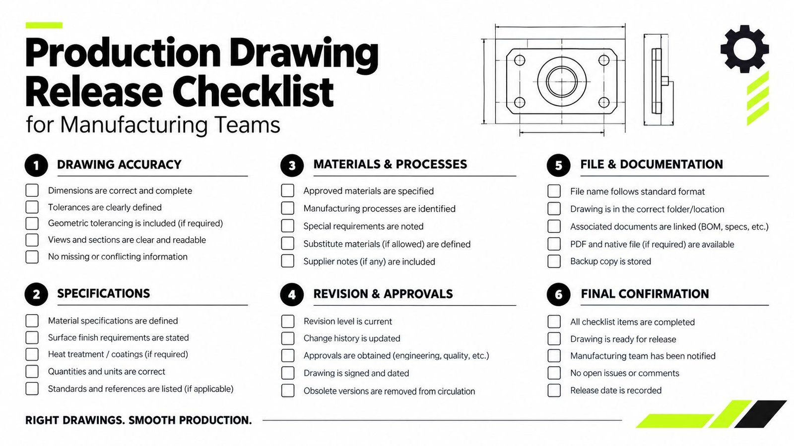
A supplier has paused production because the fixture cannot locate the part from the drawing's datum scheme. Quality has also found that an inspection characteristic has no defined acceptance method. These failures are preventable. A production drawing is ready for handoff when manufacturing, inspection, and quality can use it without relying on private assumptions. Review it as a working instruction, not only as a visual representation of the CAD model.
Confirm the technical content
Start with the features that control geometry, function, and acceptance.
- Views: Verify that orthographic, section, detail, and assembly views expose every feature required for manufacture and inspection.
- Dimensions: Check that sizes, locations, depths, angles, hole details, edge conditions, and interface characteristics are defined.
- Tolerances: Confirm that functional features have suitable limits or GD&T controls. Avoid applying unnecessary precision to non-critical features, since it can raise cost without improving function.
- Datums: Compare the datum structure with the actual fixture, assembly, and inspection setup.
- Materials: Confirm the grade, condition, treatment, and any certification or traceability requirement.
- Finishes: Identify surface finish, coating, plating, cleaning, or treatment requirements on the relevant features.
- Assemblies: Check part numbers, quantities, standard parts, bill of materials references, and assembly relationships.
A manufacturing engineer should review the drawing against the intended process. On a semi-automated station, verify that the fixture can locate the part from the stated datums, sensors can verify the required features, and the process can maintain the specified controls. A drawing that cannot be translated into fixture locations, sensor checks, or inspection steps is not ready for release. Resolve any disagreement between the equipment concept and the drawing before approval.
Check document boundaries
Keep geometry, functional characteristics, material, finish, and direct product requirements on the controlled drawing. Put operator sequences, detailed inspection methods, validation protocols, maintenance instructions, and process parameters in companion documents identified by controlled references.
This division keeps responsibilities clear. A drawing overloaded with process detail slows interpretation on the shop floor. A concise drawing with no controlled references leaves production without the instructions needed to build or inspect the part. Each requirement should appear where its responsible user will apply it, with the relationship between documents controlled.
Verify revision and approval
Review the title block, revision history, approval status, and linked documents as one release package. Confirm that the released file is the version available to the supplier, machinist, inspector, and equipment builder. Remove obsolete copies from active production locations, or mark them clearly as superseded.
- Labeling documentation: Confirm that the design history file contains the required drawing or artwork, inspection and attachment procedures, and preparer and approval signatures, as described in the standards section above.
Decide whether 2D remains the right release format
Model-based definition can make an annotated three-dimensional model the primary product definition, and CAD platforms increasingly support automated drawing generation. Traditional 2D production drawings still suit many manufacturing environments.
A 2D drawing may be the better release format when a legacy supplier works from prints, a semi-automatic workstation needs a fast visual reference, or an inspection procedure depends on explicit dimensions and traceable approval blocks. Model-based definition can work well when the organization has compatible software, disciplined annotation standards, controlled viewers, and inspection workflows that use the model reliably. AI-assisted generation can speed drafting, but human review remains necessary for datums, tolerances, document boundaries, regulatory references, and manufacturing feasibility.
Choose the format according to the downstream process, not drafting speed. Every recipient must be able to access, interpret, inspect, and control the approved product definition.
Run a cross-functional release review
Before approval, bring design, manufacturing engineering, quality, sourcing, and operations together around the actual release package. Ask each function to identify an ambiguity that could stop production or cause rework. Resolve those points in the drawing or a controlled companion document, then record the approval trail.
This review also gives automation providers the information needed to design fixtures, controls, inspection stations, and work instructions around the same approved requirements. System Engineering & Automation provides semi-automatic and fully automated equipment, custom tooling, fixtures, controls, manufacturing drawings, installation, and commissioning support for manufacturers managing real production constraints. Visit System Engineering & Automation to discuss a controlled drawing handoff and an automation solution aligned with your process, budget, and GMP-aware requirements.